HEATED STEERING WHEEL SYSTEM Steering Wheel does not Heat Up When Heated Steering Wheel Switch is Pressed
DESCRIPTION
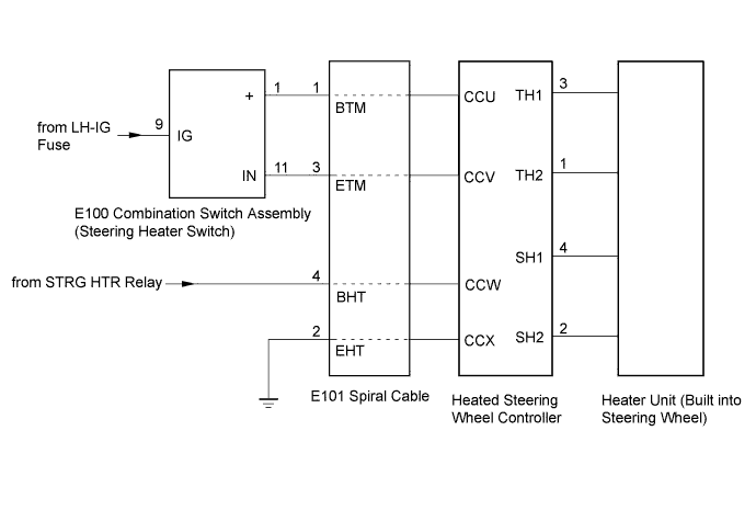
The heater unit heats the steering wheel when the combination switch is operated.
Tech Tips
-
The heater unit is built into the steering wheel.
-
As the steering wheel cannot be disassembled, replace the steering wheel when there is a malfunction in the heater unit.
WIRING DIAGRAM
INSPECTION PROCEDURE
PROCEDURE
-
CHECK COMBINATION SWITCH ASSEMBLY (LED OPERATION)
-
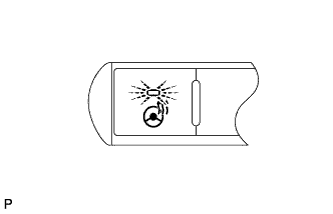
Check the illumination condition of the LED.
Result LED Condition Proceed to Blinks Engine switch on (IG)
Combination switch is pushed and held continuously for 10 seconds or more
A Illuminates Engine switch on (IG)
Combination switch is pushed
B Does not blink or illuminate Engine switch on (IG)
Combination switch is pushed
B
B 
INSPECT STEERING WHEEL ASSEMBLY (HEATER·THERMOSTAT) Click here
A 
-
-
INSPECT STEERING WHEEL ASSEMBLY (THERMISTOR)
-
Disconnect the steering wheel controller connector.
-
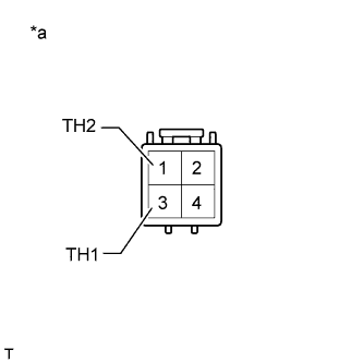
Text in Illustration *a Front view of wire harness connector
(to Heated Steering Wheel Controller)
Measure the resistance according to the value(s) in the table below.
Standard Resistance Tester Connection Condition Specified Condition 1 (TH2) - 3 (TH1) 25°C (77°F) 9.7 to 10.3 kΩ
NG 
REPLACE HEATED STEERING WHEEL CONTROLLER Click here
OK
-
-
INSPECT STEERING WHEEL ASSEMBLY (HEATER·THERMOSTAT)
-
Disconnect the steering wheel controller connector.
-
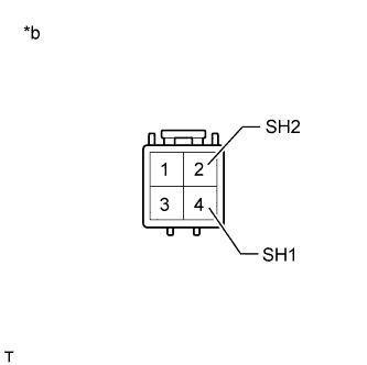
Text in Illustration *a Front view of wire harness connector
(to Heated Steering Wheel Controller)
Measure the resistance according to the value(s) in the table below.
Standard Resistance Tester Connection Condition Specified Condition 2 (SH2) - 4 (SH1) 20°C (68°F) 1.88 to 2.26 Ω
NG
REPLACE HEATED STEERING WHEEL CONTROLLER Click here
OK
-
-
CHECK HARNESS AND CONNECTOR (COMBINATION SWITCH - SPIRAL CABLE)
-
Disconnect the E100 combination switch connector.
-
Disconnect the E101 spiral cable connector.
-
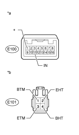
Text in Illustration *a Front view of wire harness connector
(to Combination switch)
*b Front view of wire harness connector
(to Spiral Cable)
Measure the resistance according to the value(s) in the table below.
Standard Resistance Tester Connection Condition Specified Condition E100-1 (+) - E101-1 (BTM) Always Below 1 Ω E100-11 (IN) - E101-3 (ETM) Always Below 1 Ω E101-2 (EHT) - Body ground Always Below 1 Ω -
Measure the voltage according to the value(s) in the table below.
Standard Voltage Tester Connection Switch Condition Specified Condition E101-4 (BHT) - Body ground Engine switch on (IG) 11 to 14 V
NG
REPAIR OR REPLACE WIRE HARNESS OR CONNECTOR
OK
-
-
INSPECT SPIRAL CABLE SUB-ASSEMBLY
Note
If there are any defects as mentioned below, replace the spiral cable with a new one:
Scratches, cracks, dents or chips in the connector or spiral cable.
-
Disconnect the E101 spiral cable connector.
-
Disconnect the heated steering wheel controller connector.
-
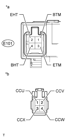
Text in Illustration *a Component without harness connected
(Spiral Cable)
*b Front view of harness connector
(to Heated Steering Wheel Controller)
Measure the resistance according to the value(s) in the table below.
Standard Resistance Tester Connection Condition Specified Condition 1 (CCU) - E101-1 (BTM) Always Below 1 Ω 2 (CCV) - E101-3 (ETM) Always Below 1 Ω 3 (CCX) - E101-2 (EHT) Always Below 1 Ω 4 (CCW) - E101-4 (BHT) Always Below 1 Ω
NG
REPLACE SPIRAL CABLE SUB-ASSEMBLY Click here
OK
-
-
CHECK COMBINATION SWITCH ASSEMBLY
-
Disconnect the combination switch connector.
-
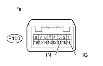
Text in Illustration *a Component without harness connected
(to Combination switch)
Measure the voltage according to the value(s) in the table below.
Tech Tips
As the circuit has a diode, perform the measurement in diode test mode and make sure that the polarity is correct.
Standard Voltage Tester Connection
Positive (+) tester probe - Negative (-) tester probe
Switch Condition Specified Condition E100-9 (IG) - E100-11 (IN) Combination switch is pushed Below 1.25 V
NG
REPLACE COMBINATION SWITCH ASSEMBLY Click here
OK 
REPLACE HEATED STEERING WHEEL CONTROLLER Click here
-