HEATED STEERING WHEEL SYSTEM TERMINALS OF ECU

-
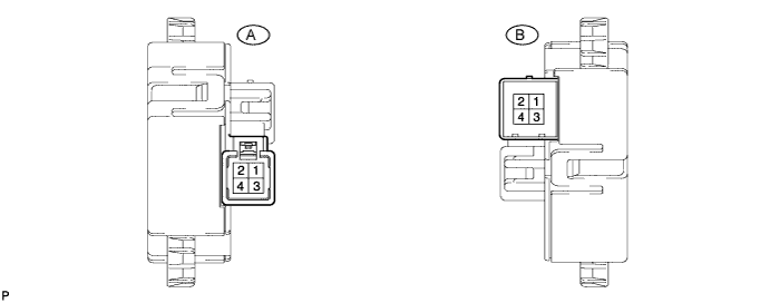
CHECK HEATED STEERING WHEEL CONTROLLER
Tech Tips
Inspect the connectors from the back side while the connectors are connected.
-
Measure the voltage and resistance according to the value(s) in the table below.
Terminal No. (Symbol) Wiring Color Terminal Description Condition Specified Condition A-4 (CCW) - A-3 (CCX) W - GR IG power supply Engine switch on (IG) 11 to 14 V A-1 (CCU) - A-3 (CCX) BR - GR Heated steering wheel switch LED output signal Engine switch on (IG), Steering heater switch on Below 3 V A-2 (CCV) - A-3 (CCX) G - GR Heated steering wheel switch input signal Engine switch on (IG), Steering heater switch pressed and held 10 to 14 V B-3 (TH1) - A-3 (CCX) G - GR Thermistor input signal Engine switch on (IG), Steering heater switch on at 0 to 40°C (32 to 104°F) 1.5 to 4.5 V B-1 (TH2) - A-3 (CCX) G - GR Thermistor ground Engine switch on (IG), Steering heater switch on Below 1 V B-4 (SH1) - A-3 (CCX) R - GR Heater ground Engine switch on (IG), Steering heater switch on Below 1 V B-2 (SH2) - A-3 (CCX) B - GR Heater output signal Engine switch on (IG), Steering heater switch on 10 to 14 V* A-3 (CCX) - Body ground GR - Body ground Ground Always Below 1 Ω Tech Tips
*: The current to the heater turns on/off depending on the temperature of the thermistor. As a result, it may take several minutes before a voltage value is output.
-