POWER TILT AND POWER TELESCOPIC STEERING COLUMN SYSTEM IG Power Source Circuit
DESCRIPTION
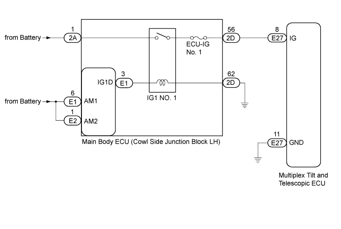
When the engine switch is turned on (IG), the IG power source circuit supplies positive (+) voltage to the multiplex tilt and telescopic ECU.
The multiplex tilt and telescopic ECU also receives engine switch signals via this circuit.
WIRING DIAGRAM
INSPECTION PROCEDURE
PROCEDURE
-
INSPECT FUSE (ECU-IG1 No. 1)
-
Remove the ECU-IG1 No. 1 fuse from the main body ECU.
-
Measure the resistance of the fuse.
Standard Resistance Tester Connection Condition Specified Condition ECU-IG1 No. 1 fuse Always Below 1 Ω
NG 
REPLACE FUSE
OK 
-
-
CHECK MULTIPLEX TILT AND TELESCOPIC ECU (IG TERMINAL VOLTAGE)
-
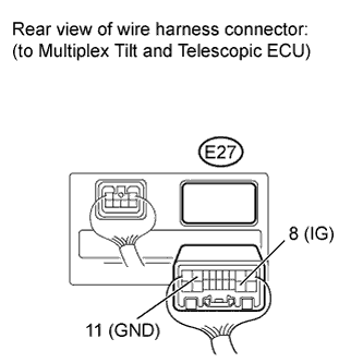
Disconnect the E27 connector from the multiplex tilt and telescopic ECU.
-
Measure the voltage according to the value(s) in the table below.
Standard Voltage Tester Connection Switch Condition Specified Condition E27-8 (IG) - E27-11 (GND) Engine switch on (IG) 11 to 14 V
NG 
CHECK HARNESS AND CONNECTOR (MULTIPLEX TILT AND TELESCOPIC ECU - BODY GROUND) Click here
OK 
REPLACE MULTIPLEX TILT AND TELESCOPIC ECU Click here
-
-
CHECK HARNESS AND CONNECTOR (MULTIPLEX TILT AND TELESCOPIC ECU - BODY GROUND)
-
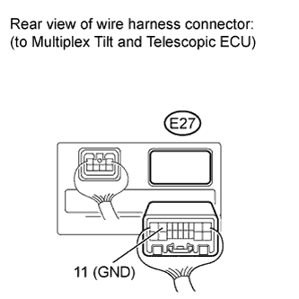
Measure the resistance according to the value(s) in the table below.
Standard Resistance Tester Connection Condition Specified Condition E27-11 (GND) - Body ground Always Below 1 Ω
NG
REPAIR OR REPLACE HARNESS OR CONNECTOR
OK
-
-
CHECK HARNESS AND CONNECTOR (MULTIPLEX TILT AND TELESCOPIC ECU - MAIN BODY ECU)
-
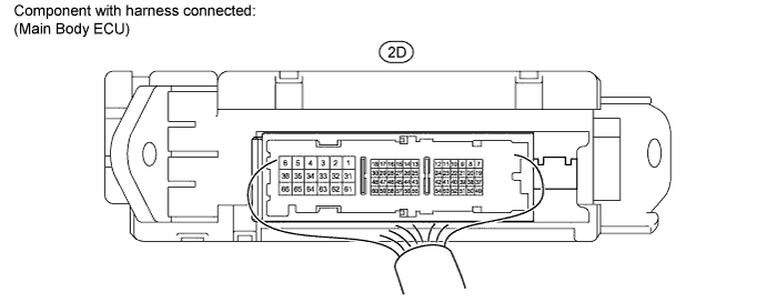
Measure the voltage according to the value(s) in the table below.
Standard Voltage Tester Connection Switch Condition Specified Condition 2D-56 - Body ground Engine switch on (IG) 11 to 14 V
NG
REPAIR OR REPLACE HARNESS OR CONNECTOR (MAIN BODY ECU - BATTERY)
OK
REPAIR OR REPLACE HARNESS OR CONNECTOR (MULTIPLEX TILT AND TELESCOPIC ECU - MAIN BODY ECU)
-