PARKING BRAKE CABLE INSTALLATION

Tech Tips
-
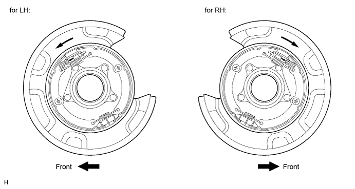
Use the same procedures for the LH side and RH side.
-
The procedures listed below are for the LH side.
-
INSTALL NO. 2 PARKING BRAKE CABLE ASSEMBLY
-
Install the No. 2 parking brake cable clamp.
-
Install the No. 2 parking brake cable with the 6 bolts.
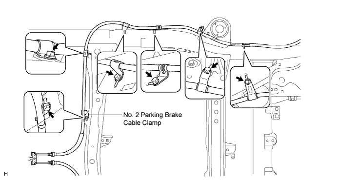
- Torque:
- 13 N*m { 127 kgf*cm, 9 ft.*lbf }
-
Install the fuel tank Click here.
-
Attach the claws of the No. 2 parking brake cable.
-
Connect the No. 2 parking brake cable to the No. 1 parking brake pull rod.
-
-
INSTALL NO. 3 PARKING BRAKE CABLE ASSEMBLY
-
Install the No. 3 parking brake cable clamp.
-
Install the No. 3 parking brake cable with the 6 bolts.
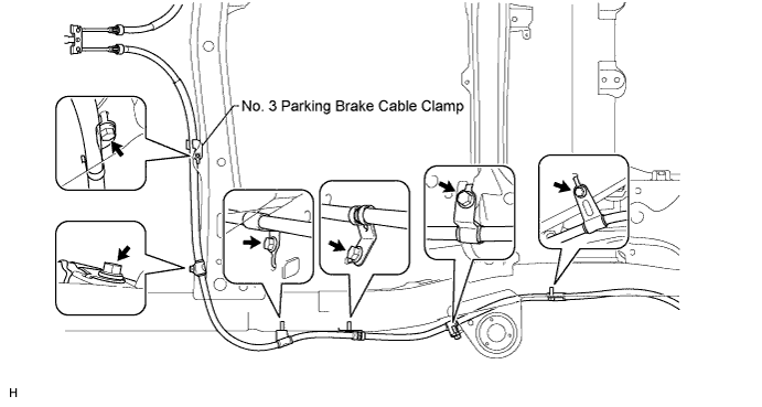
- Torque:
- 13 N*m { 127 kgf*cm, 9 ft.*lbf }
-
Attach the claws of the No. 3 parking brake cable.
-
Connect the No. 3 parking brake cable to the No. 1 parking brake pull rod.
-
-
CONNECT NO. 3 PARKING BRAKE CABLE ASSEMBLY
-
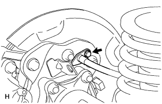
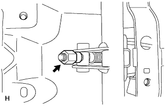
Connect the No. 3 parking brake cable with the bolt.
- Torque:
- 8.0 N*m { 82 kgf*cm, 71 in.*lbf }
-
-
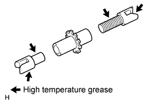
INSTALL PARKING BRAKE SHOE LEVER
-
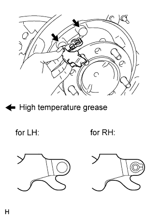
Apply high temperature grease to the parking brake anchor block.
-
Install the parking brake shoe lever to the No. 3 parking brake cable.
Note
Be carefully to distinguish between the parking brake shoe lever RH and LH.
-
-
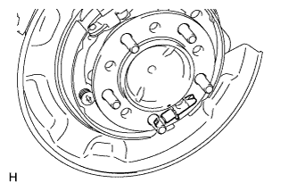
INSTALL NO. 2 PARKING BRAKE SHOE ASSEMBLY
-
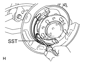
Using SST, install the No. 2 parking brake shoe with the shoe hold down spring pin, compression spring and shoe hold down spring cup.
- SST
- 09718-00011
-
-
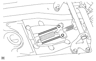
INSTALL NO. 1 PARKING BRAKE SHOE ASSEMBLY
-
Apply high temperature grease to the thread and all joining areas of the parking brake shoe adjuster screw set.
-
Set the No. 1 parking brake shoe and shoe adjuster screw set in place.
-
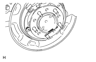
Connect the tension spring.
-
Using SST, install the shoe hold down spring pin, compression spring and shoe hold down spring cup.
- SST
- 09718-00011
-
-
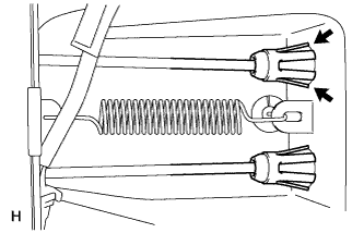
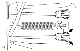
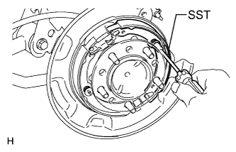
INSTALL PARKING BRAKE SHOE RETURN SPRING
-
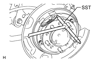
Using SST, install the shoe return spring.
- SST
- 09703-30011
-
-
CHECK PARKING BRAKE INSTALLATION
-
Check that each part is installed properly.
-
-
INSTALL REAR DISC
- Torque:
- 131 N*m { 1336 kgf*cm, 97 ft.*lbf }
-
CONNECT REAR DISC BRAKE CYLINDER ASSEMBLY
-
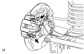
Connect the rear disc brake cylinder with 2 new bolts.
- Torque:
- 95 N*m { 969 kgf*cm, 70 ft.*lbf }
Note
-
Do not twist the brake hose.
-
Make sure that the bolts are free from damage and foreign matter.
-
Do not overtighten the bolts.
-
-
INSTALL REAR NO. 2 SUSPENSION CONTROL ACCUMULATOR BRACKET
-
Install the bracket to the shock absorber control valve with the bolt.
- Torque:
- 18 N*m { 184 kgf*cm, 13 ft.*lbf }
-
-
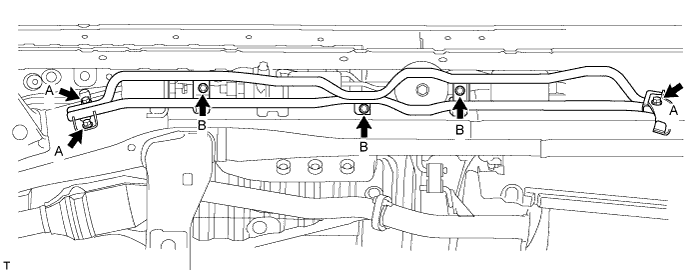
INSTALL HEIGHT CONTROL UNIT PROTECTOR PIPE
-
Install the protector pipe with the 6 bolts.
- Torque:
- for bolt A
- 31 N*m { 316 kgf*cm, 23 ft.*lbf }
- for bolt B
- 16 N*m { 163 kgf*cm, 12 ft.*lbf }
-
-
INSPECT PARKING BRAKE LEVER TRAVEL
-
Fully pull the parking brake lever to engage the parking brake.
-
Release the lever to disengage the parking brake.
-
Slowly pull the parking brake lever all the way, and count the number of clicks.
Standard Parking Brake Lever Travel when Pulled with a Force of 200 N (20 kgf, 45 lbf) 5 to 7 clicks If the parking brake lever travel is not as specified, adjust the parking brake shoe clearance and parking brake lever travel.
-
-
ADJUST PARKING BRAKE LEVER TRAVEL
-
Remove the console cup holder box sub-assembly Click here.
-
Completely release the parking brake lever.
-
Loosen the adjusting nut to completely release the parking brake cable.
-
Temporarily install the hub nuts.
-
Remove the hole plug.
-
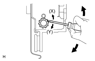
Insert an adjustment tool into the adjustment hole of the disc. Rotate the adjustment wheel in the "X" direction until the shoes are locked. Then rotate the adjustment wheel in the "Y" direction 8 notches.
-
Check that the disc can be rotated lightly. If not, rotate the adjustment wheel in the "Y" direction and check again.
-
Install the hole plug.
-
Remove the hub nuts.
-
Turn the adjusting nut until the parking brake lever travel becomes correct.
Standard Parking Brake Lever Travel when Pulled with a Force of 200 N (20 kgf, 45 lbf) 5 to 7 clicks -
Operate the parking brake lever 3 to 4 times, and check the parking brake lever travel.
Standard Parking Brake Lever Travel when Pulled with a Force of 200 N (20 kgf, 45 lbf) 5 to 7 clicks -
Check whether the parking brake drags or not.
-
When operating the parking brake lever, check that the brake warning light comes on.
Standard Condition The brake warning light always illuminates at the first click. -
Install the console cup holder box sub-assembly Click here.
-
-
INSTALL REAR WHEEL
- Torque:
- 131 N*m { 1336 kgf*cm, 97 ft.*lbf }
-
INSTALL REAR CONSOLE BOX SUB-ASSEMBLY (w/o Cool Box)
-
Install the rear console box sub-assembly Click here.
-
-
INSTALL COOLING BOX ASSEMBLY (w/ Cool Box)
-
Install the cooling box assembly Click here.
-
-
INSTALL FRONT SEAT ASSEMBLY LH (w/ Cool Box)
-
Install the front seat assembly LH Click here.
-
-
CHARGE REFRIGERANT (w/ Cool Box)
- SST
- 09985-20010 ( 09985-02130, 09985-02150, 09985-02090, 09985-02110, 09985-02010, 09985-02050, 09985-02060, 09985-02070 )
-
Perform vacuum purging using a vacuum pump.
-
Charge refrigerant HFC-134a (R134a).
Standard: Condenser Core Thickness Cool Box Refrigerant Charging Amount 22 mm (0.866 in.) w/ Cool Box 1010 +/-30 g (35.6 +/-1.1 oz.) w/o Cool Box 970 +/-30 g (34.2 +/-1.1 oz.) 16 mm (0.630 in.) w/ Cool Box 970 +/-30 g (34.2 +/-1.1 oz.) w/o Cool Box 920 +/-30 g (32.5 +/-1.1 oz.) 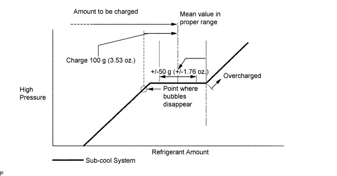
Note
-
Do not operate the cooler compressor before charging refrigerant as the cooler compressor will not work properly without any refrigerant, and will overheat.
-
Approximately 100 g (3.53 oz.) of refrigerant may need to be charged after bubbles disappear. The refrigerant amount should be checked by measuring its quantity, and not with the sight glass.
-
-
WARM UP ENGINE (w/ Cool Box)
-
Warm up the engine at less than 1850 rpm for 2 minutes or more after charging the refrigerant.
Note
Be sure to warm up the compressor when turning the A/C switch on after removing and installing the cooler refrigerant lines (including the compressor), to prevent damage to the compressor.
-
-
CHECK FOR REFRIGERANT GAS LEAK (w/ Cool Box)
-
After recharging the refrigerant gas, check for refrigerant gas leakage using a halogen leak detector.
-
Perform the operation under these conditions:
-
Stop the engine.
-
Secure good ventilation (the halogen leak detector may react to volatile gases other than refrigerant, such as evaporated gasoline or exhaust gas).
-
Repeat the test 2 or 3 times.
-
Make sure that some refrigerant remains in the refrigeration system. When compressor is off: approximately 392 to 588 kPa (4.0 to 6.0 kgf/cm2, 57 to 85 psi).
-
-
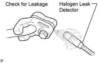
Using a halogen leak detector, check the refrigerant line for leakage.
-
If a gas leak is not detected on the drain hose, remove the blower motor control (blower resistor) from the cooling unit. Insert the halogen leak detector sensor into the unit and perform the test.
-
Disconnect the connector and wait for approximately 20 minutes. Bring the halogen leak detector close to the pressure switch and perform the test.
-
-
INSTALL UPPER RADIATOR SUPPORT SEAL (w/ Cool Box)
-
Install the upper radiator support seal with the 3 clips.
-
-
CLEAN ENGINE ROOM SIDE COVER RH (w/ Cool Box)
-
Install the engine room side cover RH with the 7 clips.
-
-
INSTALL ENGINE ROOM SIDE COVER LH (w/ Cool Box)
-
Install the engine room side cover LH with the 7 clips.
-