HYDRAULIC BRAKE BOOSTER (for LHD) INSTALLATION

-
INSTALL BRAKE BOOSTER GASKET
-
Install a new brake booster gasket to the hydraulic brake booster.
-
-
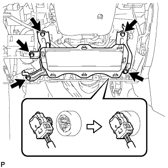
INSTALL HYDRAULIC BRAKE BOOSTER ASSEMBLY
-
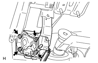
Install the hydraulic brake booster assembly with the 4 nuts.
- Torque:
- 14 N*m { 145 kgf*cm, 10 ft.*lbf }
-
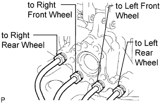
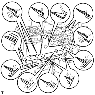
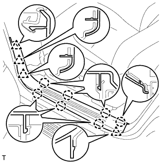
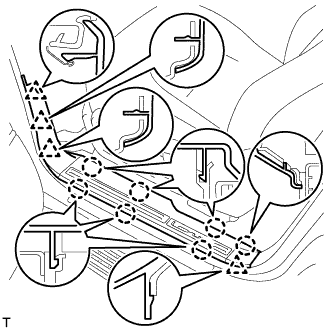
Connect the 4 brake lines to the correct positions on the hydraulic brake booster assembly as shown in the illustration.
-
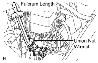
Using a union nut wrench, tighten the 4 brake lines.
- Torque:
- without union nut wrench
- 15 N*m { 155 kgf*cm, 11 ft.*lbf }
- with union nut wrench
- 14 N*m { 145 kgf*cm, 10 ft.*lbf }
Tech Tips
-
Use a torque wrench with a fulcrum length of 300 mm (11.8 in.).
-
The torque value for use with a union nut wrench is effective when the union nut wrench is parallel to the torque wrench.
-
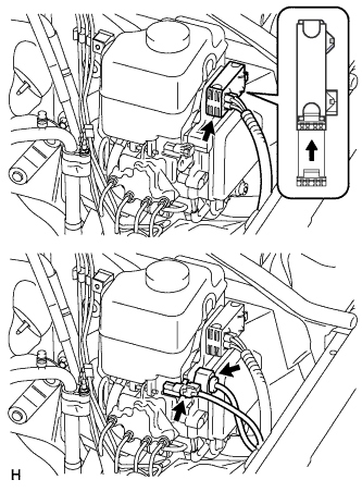
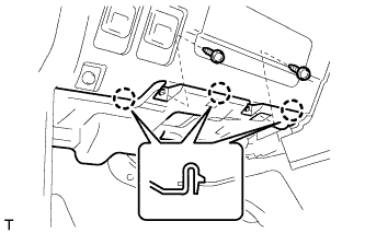
Connect the 3 connectors to the hydraulic brake booster.
-
-
INSTALL PUSH ROD PIN
-
Apply a light coat of lithium soap base glycol grease to the inner surface of the hole on the brake pedal lever.
-
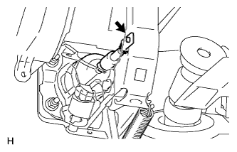
Set the master cylinder push rod clevis in place, insert the push rod pin from the outside of the vehicle and then install a new clip.
-
-
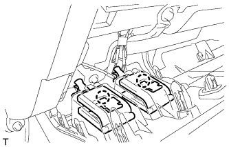
INSTALL DRIVER SIDE KNEE AIRBAG ASSEMBLY
-
Connect the connector.
Note
When handling the airbag connector, take care not to damage the airbag wire harness.
-
Install the driver side knee airbag with the 5 bolts.
- Torque:
- 10 N*m { 102 kgf*cm, 7 ft.*lbf }
-
-
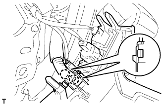
INSTALL LOWER NO. 1 INSTRUMENT PANEL FINISH PANEL
-
Connect the connectors.
-
Attach the 2 claws to install the sensor.
-
Attach the 2 claws to connect the 2 control cables.
-
Attach the 16 claws to install the finish panel.
-
Install the 2 bolts.
-
Attach the 2 claws to close the hole cover.
-
-
INSTALL COWL SIDE TRIM BOARD LH
-
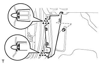
Attach the 2 clips to install the trim board.
-
Install the cap nut.
-
-
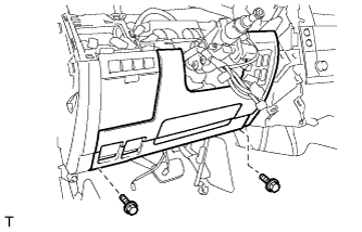
INSTALL NO. 1 INSTRUMENT PANEL UNDER COVER SUB-ASSEMBLY
-
Connect the connectors.
-
Attach the 3 claws to install the under cover.
-
Install the 2 screws.
-
-
INSTALL FRONT DOOR SCUFF PLATE LH
-
w/o Illumination:
-
Attach the 7 claws and 4 clips to install the scuff plate.
-
-
w/ Illumination:
-
Connect the connector.
-
Attach the 7 claws and 4 clips to install the scuff plate.
-
-
-
CONNECT CABLE TO NEGATIVE BATTERY TERMINAL
Note
When disconnecting the cable, some systems need to be initialized after the cable is reconnected Click here.
-
BLEED BRAKE SYSTEM
CAUTION:
If air is bled without using the intelligent tester, damage or accidents may result. Therefore, always use the intelligent tester when bleeding air.
-
Turn the ignition switch to ON.
-
Remove the brake master cylinder reservoir filler cap assembly.
-
Add brake fluid until the fluid level is between the MIN and MAX lines of the reservoir.
-
Repeatedly depress the brake pedal and bleed air from the bleeder plug of the front disc brake cylinder RH.
-
Repeat the step above until the air is completely bled, and then tighten the bleeder plug while depressing the brake pedal.
- Torque:
- 11 N*m { 110 kgf*cm, 8 ft.*lbf }
-
Bleed the air from the bleeder plug of the front disc brake cylinder LH using the same procedure as for the RH side.
-
With the brake pedal depressed, loosen the bleeder plug of the rear disc brake cylinder RH, continue to hold the brake pedal and allow brake fluid to be drained from the bleeder plug while the pump motor operates.
Tech Tips
-
Air is bled as the pump motor operates while the brake pedal is being depressed.
-
Be sure to release the brake pedal to stop the motor after approximately 100 seconds of continuous operation.
-
As brake fluid is continuously drained while the pump operates, it is not necessary to repeatedly depress the brake pedal.
-
-
When there is no more air in the brake fluid, tighten the bleeder plug, and then release the brake pedal.
- Torque:
- 11 N*m { 110 kgf*cm, 8 ft.*lbf }
-
Bleed the air from the bleeder plug of the rear disc brake cylinder LH using the same procedure as for the RH side.
-
Turn the ignition switch off and connect the intelligent tester to the DLC3.
-
Turn the ignition switch to ON.
-
Turn the intelligent tester on.
-
Enter the following menus: Chassis / ABS/VSC/TRC / Utility / Air Bleeding.
Note
To protect the solenoid from overheating, the solenoid operation stops automatically in 4 seconds, and then the solenoid will not respond to commands for an additional 20 seconds.
-
Repeatedly depress the brake pedal several times, and then, with the brake pedal depressed, turn FR on and bleed air.
Tech Tips
Air returns to the brake master cylinder reservoir together with the brake fluid and is bled from the brake system.
Note
-
As it is not possible to visually confirm that air is being bled, repeat this step 10 times.
-
Do not loosen the bleeder plug.
-
-
Turn FL on and bleed air using the same procedures as for FR.
-
Turn RR on, loosen the bleeder plug of the rear disc brake cylinder RH and drain brake fluid.
Tech Tips
-
Do not depress the brake pedal.
-
As brake fluid is automatically drained while the pump and solenoid operate, it is not necessary to operate the brake pedal.
-
-
Repeat the step above until the air is completely bled, and then tighten the bleeder plug.
- Torque:
- 11 N*m { 110 kgf*cm, 8 ft.*lbf }
-
Turn FL Line on and bleed the air from the bleeder plug of the front disc brake cylinder LH using the same procedure as for the RH side.
-
Turn RR Line on and loosen the bleeder plug of the rear disc brake cylinder RH.
Tech Tips
Be sure to bleed air with the brake pedal depressed.
-
Repeat the step above until the air is completely bled, and then tighten the bleeder plug.
- Torque:
- 11 N*m { 110 kgf*cm, 8 ft.*lbf }
-
Turn RL Line on and bleed air from the bleeder plug of the rear disc brake cylinder LH using the same procedure as for the RH side.
-
Turn the intelligent tester off and turn the ignition switch off.
-
Inspect for brake fluid leaks.
-
Check and adjust the brake fluid level Click here.
-
Clear the DTCs Click here.
-
-
CHECK BRAKE PEDAL HEIGHT
-
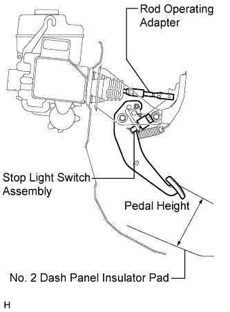
Check the brake pedal height.
Standard Pedal Height from No. 2 Dash Panel Insulator Pad 147.1 to 157.1 mm (5.80 to 6.18 in.) Note
Do not adjust the pedal height. Doing so by changing the push rod length will structurally change the pedal ratio.
If the pedal height is incorrect, adjust the rod operating adapter length.
-
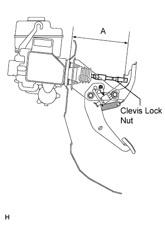
Adjust the rod operating adapter length.
-
Remove the clip and clevis pin.
-
Loosen the clevis lock nut.
-
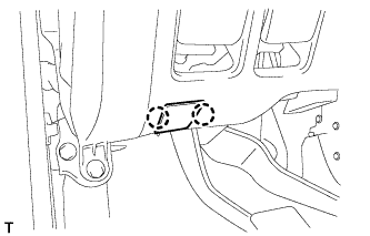
Adjust the rod operating adapter length by turning the pedal push rod clevis.
Standard Rod Operating Adapter Length "A" 201.7 to 202.7 mm (7.94 to 7.98 in.) -
Tighten the clevis lock nut.
- Torque:
- 26 N*m { 260 kgf*cm, 19 ft.*lbf }
-
Set the master cylinder push rod clevis in place, insert the push rod pin from the outside of the vehicle and then install a new clip.
If the pedal height is incorrect even if the rod operating adapter is adjusted, check that there is no damage to the brake pedal, brake pedal lever, brake pedal support and dash panel.
-
Even if there is damage, there is no problem if the reserve distance is within the standard value.
-
If necessary, replace any damaged parts.
-
-
-
-
CHECK PEDAL FREE PLAY
-
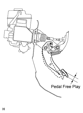
Push in the pedal until resistance is felt. Measure the free play as shown in the illustration.
Standard Pedal Free Play 1 to 6 mm (0.0394 to 0.236 in.)
-
-
CHECK PEDAL RESERVE DISTANCE
-
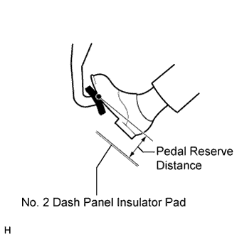
Release the parking brake lever. With the engine running, depress the pedal and measure the pedal reserve distance as shown in the illustration.
Standard Pedal Reserve Distance from No. 2 Dash Panel Insulator Pad at 490 N (50 kgf, 110.2 lbf) More than 67 mm (2.64 in.) If incorrect, troubleshoot the brake system.
-
-
INSPECT BRAKE MASTER CYLINDER OPERATION
-
Inspect the brake master cylinder operation Click here.
-