LIGHTING SYSTEM Stop Light does not Illuminate
DESCRIPTION
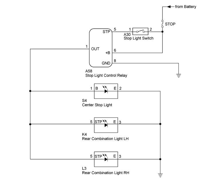
When the stop light switch is turned on, current flows to the stop lights to illuminate them.
WIRING DIAGRAM
INSPECTION PROCEDURE
Note
Inspect the fuses for circuits related to this system before performing the following inspection procedure.
PROCEDURE
-
INSPECT STOP LIGHT SWITCH
-
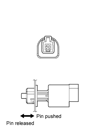
Remove the stop light switch Click here.
-
Measure the resistance according to the value(s) in the table below.
Standard Resistance Tester Connection Switch Condition Specified Condition 1 - 2 Switch pin released Below 1 Ω 1 - 2 Switch pin pushed in 10 kΩ or higher
NG 
REPLACE STOP LIGHT SWITCH Click here
OK 
-
-
CHECK HARNESS AND CONNECTOR (STOP LIGHT SWITCH - STOP LIGHT CONTROL RELAY BATTERY AND BODY GROUND)
-
Disconnect the A58 stop light control relay connector.
-
Disconnect the A30 stop light switch connector.
-
Measure the voltage according to the value(s) in the table below.
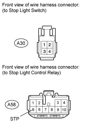
Standard Voltage Tester Connection Condition Specified Condition A30-2 - Body ground Always 11 to 14 V -
Measure the resistance according to the value(s) in the table below.
Standard Resistance Tester Connection Condition Specified Condition A30-1 - A58-5 (STP) Always Below 1 Ω A30-1 - Body ground Always 10 kΩ or higher
NG
REPAIR OR REPLACE HARNESS OR CONNECTOR
OK
-
-
CHECK HARNESS AND CONNECTOR (STOP LIGHT CONTROL RELAY - BATTERY AND BODY GROUND)
-
Disconnect the A58 stop light control relay connector.
-
Measure the voltage according to the value(s) in the table below.
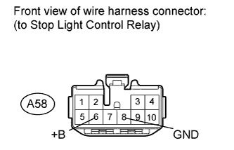
Standard Voltage Tester Connection Condition Specified Condition A58-6 (+B) - Body ground Always 11 to 14 V -
Measure the resistance according to the value(s) in the table below.
Standard Resistance Tester Connection Condition Specified Condition A58-8 (GND) - Body ground Always Below 1 Ω
NG
REPAIR OR REPLACE HARNESS OR CONNECTOR
OK
-
-
CHECK HARNESS AND CONNECTOR (CENTER STOP LIGHT - STOP LIGHT CONTROL RELAY AND BODY GROUND)
-
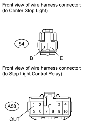
Disconnect the A58 stop light control relay connector.
-
Disconnect the S4 center stop light connector.
-
Measure the resistance according to the value(s) in the table below.
Standard Resistance Tester Connection Condition Specified Condition A58-1 (OUT) - S4-1 (B) Always Below 1 Ω S4-2 (E) - Body ground Always Below 1 Ω A58-1 (OUT) - Body ground Always 10 kΩ or higher
NG
REPAIR OR REPLACE HARNESS OR CONNECTOR
OK 
REPLACE STOP LIGHT CONTROL RELAY
-