LIGHTING SYSTEM Back-up Light does not Illuminate
DESCRIPTION
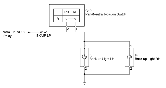
The park/neutral position switch turns on when the shift lever is moved to R, causing the back-up lights to illuminate.
WIRING DIAGRAM
INSPECTION PROCEDURE
PROCEDURE
-
INSPECT PARK/NEUTRAL POSITION SWITCH
-
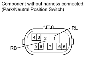
Remove the park/neutral position switch Click here.
-
Measure the resistance according to the value(s) in the table below.
Standard Resistance Tester Connection Condition Specified Connection 2 (RB) - 1 (RL) Shift lever in R Below 1 Ω 2 (RB) - 1 (RL) Shift lever not in R 10 kΩ or higher
NG 
REPLACE PARK/NEUTRAL POSITION SWITCH Click here
OK 
-
-
CHECK HARNESS AND CONNECTOR (PARK/NEUTRAL POSITION SWITCH - BATTERY)
-
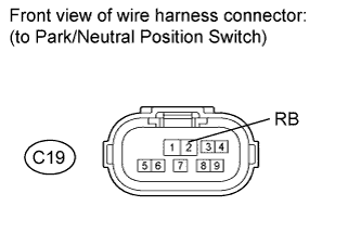
Disconnect the C19 switch connector.
-
Measure the voltage according to the value(s) in the table below.
Standard Voltage Tester Connection Switch Condition Specified Condition C19-2 (RB) - Body ground Engine switch on (IG) 11 to 14 V
NG
REPAIR OR REPLACE HARNESS OR CONNECTOR
OK
-
-
CHECK HARNESS AND CONNECTOR (BACK-UP LIGHT - PARK/NEUTRAL POSITION SWITCH AND BODY GROUND)
-
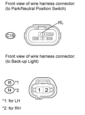
Disconnect the C19 switch connector.
-
Disconnect the f4 and f5 light connectors.
-
Measure the resistance according to the value(s) in the table below.
Standard Resistance for LH Tester Connection Condition Specified Condition C19-1 (RL) - f5-1 Always Below 1 Ω f5-2 - Body ground f5-1 - Body ground Always 10 kΩ or higher for RH Tester Connection Condition Specified Condition C19-1 (RL) - f4-1 Always Below 1 Ω f4-2 - Body ground f4-1 - Body ground Always 10 kΩ or higher
NG
REPAIR OR REPLACE HARNESS OR CONNECTOR
OK 
REPLACE BACK-UP LIGHT Click here
-