LIGHTING SYSTEM LO-beam Headlight does not Illuminate
DESCRIPTION
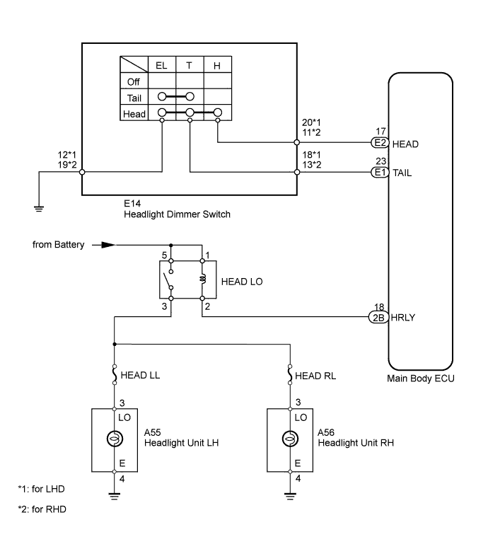
The main body ECU receives a headlight switch information signal from the light control switch, and illuminates the headlight low beam.
WIRING DIAGRAM
INSPECTION PROCEDURE
PROCEDURE
-
READ VALUE USING INTELLIGENT TESTER (HEADLIGHT DIMMER SWITCH)
-
Using the intelligent tester, read the Data List Click here.
Main Body Tester Display Measurement Item/Range Normal Condition Diagnostic Note Head Light SW (HEAD) Headlight switch signal/ON or OFF ON: Headlight switch (Head) on
OFF: Headlight switch (Head) off
- OK When the headlight dimmer switch operation is performed, the result will be the same as above.
NG 
INSPECT HEADLIGHT DIMMER SWITCH Click here
OK 
-
-
PERFORM ACTIVE TEST USING INTELLIGENT TESTER (HEADLIGHT)
-
Using the intelligent tester, perform the Active Test Click here.
Main Body Tester Display Test Part Control Range Diagnostic Note Headlight Relay Headlight ON/OFF - OK Headlight low beam turns on/off.
NG
INSPECT HEADLIGHT RELAY (HEAD LO) Click here
OK 
REPLACE MAIN BODY ECU
-
-
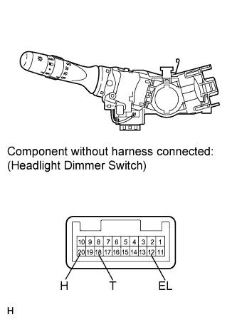
INSPECT HEADLIGHT DIMMER SWITCH
-
for LHD:
-
Remove the headlight dimmer switch Click here.
-
Measure the resistance according to the value(s) in the table below.
Standard Resistance Tester Connection Switch Condition Specified Condition 20 (H) - 12 (EL) Headlight dimmer switch (Light control switch) head Below 1 Ω 18 (T) - 12 (EL) 20 (H) - 12 (EL) Headlight dimmer switch (Light control switch) off 10 kΩ or higher 18 (T) - 12 (EL)
-
-
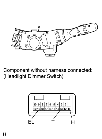
for RHD:
-
Remove the headlight dimmer switch Click here.
-
Measure the resistance according to the value(s) in the table below.
Standard Resistance Tester Connection Switch Condition Specified Condition 11 (H) - 19 (EL) Headlight dimmer switch (Light control switch) head Below 1 Ω 13 (T) - 19 (EL) 11 (H) - 19 (EL) Headlight dimmer switch (Light control switch) off 10 kΩ or higher 13 (T) - 19 (EL) Result Result Proceed to OK A NG (for LHD) B NG (for RHD) C
-
B 
REPLACE HEADLIGHT DIMMER SWITCH Click here
C
REPLACE HEADLIGHT DIMMER SWITCH Click here
A
-
-
CHECK HARNESS AND CONNECTOR (HEADLIGHT DIMMER SWITCH - MAIN BODY ECU AND BODY GROUND)
-
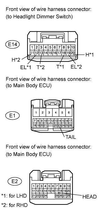
Disconnect the E14 switch connector.
-
Disconnect the E1 and E2 ECU connectors.
-
Measure the resistance according to the value(s) in the table below.
Standard Resistance for LHD Tester Connection Condition Specified Condition E14-20 (H) - E2-17 (HEAD) Always Below 1 Ω E14-18 (T) - E1-23 (TAIL) E14-12 (EL) - Body ground E14-20 (H) - Body ground Always 10 kΩ or higher E14-18 (T) - Body ground for RHD Tester Connection Condition Specified Condition E14-11 (H) - E2-17 (HEAD) Always Below 1 Ω E14-13 (T) - E1-23 (TAIL) E14-19 (EL) - Body ground E14-11 (H) - Body ground Always 10 kΩ or higher E14-18 (T) - Body ground
NG
REPAIR OR REPLACE HARNESS OR CONNECTOR
OK
REPLACE MAIN BODY ECU
-
-
INSPECT HEADLIGHT RELAY (HEAD LO)
-
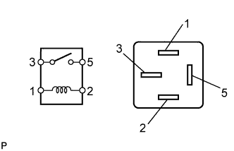
Remove the HEAD LO relay from the engine room relay block.
-
Measure the resistance according to the value(s) in the table below.
Standard Resistance Tester Connection Condition Specified Condition 3 - 5 Battery voltage not applied to terminals 1 and 2 10 kΩ or higher Battery voltage applied to terminals 1 and 2 Below 1 Ω
NG
REPLACE HEAD LO RELAY
OK
-
-
CHECK HARNESS AND CONNECTOR (HEADLIGHT RELAY [HEAD LO] - BATTERY)
-
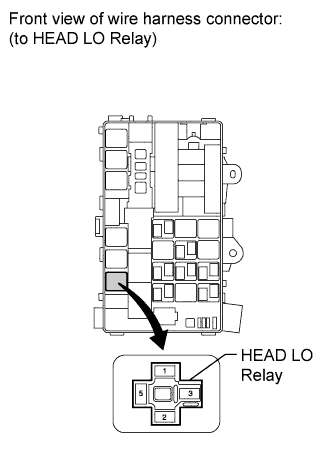
Remove the HEAD LO relay from the engine room relay block.
-
Measure the voltage according to the value(s) in the table below.
Standard Voltage Tester Connection Switch Condition Specified Condition HEAD LO Relay terminal 1 - Body ground Engine switch on (IG) 11 to 14 V HEAD LO Relay terminal 5 - Body ground
NG
REPAIR OR REPLACE HARNESS OR CONNECTOR
OK
-
-
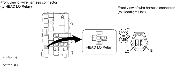
CHECK HARNESS AND CONNECTOR (HEADLIGHT - HEAD LO RELAY AND BODY GROUND)
-
Remove the HEAD LO relay from the engine room relay block.
-
Disconnect the A55*1 or A56*2 light connector.
-
*1: for LH
-
*2: for RH
-
-
Measure the resistance according to the value(s) in the table below.
Standard Resistance for LH Tester Connection Condition Specified Condition HEAD LO relay terminal 3 - A55-3 (LO) Always Below 1 Ω A55-4 (E) - Body ground A55-3 (LO) - Body ground Always 10 kΩ or higher for RH Tester Connection Condition Specified Condition HEAD LO relay terminal 3 - A56-3 (LO) Always Below 1 Ω A56-4 (E) - Body ground A56-3 (LO) - Body ground Always 10 kΩ or higher
NG
REPAIR OR REPLACE HARNESS OR CONNECTOR
OK
-
-
CHECK HEADLIGHT (LOW BEAM)
-
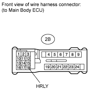
Disconnect the 2B ECU connector.
-
Using a service wire, connect terminal 2B-18 (HRLY) on the wire harness side and the body ground.
-
Check that the headlight low beam illuminates.
OK Headlight low beam illuminates.
NG
REPAIR OR REPLACE HARNESS OR CONNECTOR (HEADLIGHT RELAY - MAIN BODY ECU)
OK
REPLACE MAIN BODY ECU
-