LIGHTING SYSTEM Inside Handle Light does not Illuminate
WIRING DIAGRAM
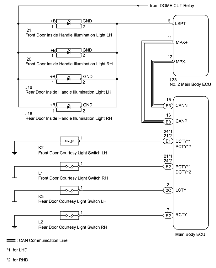
INSPECTION PROCEDURE
Note
First perform the communication function inspections in How to Proceed with Troubleshooting to confirm that there are no CAN communication malfunctions before troubleshooting this symptom.
PROCEDURE
-
READ VALUE USING INTELLIGENT TESTER (DOOR COURTESY LIGHT SWITCH)
-
Using the intelligent tester, read the Data List.
Main Body Tester Display Test Part Control Range Diagnostic Note D Door Courtesy SW Front door courtesy light switch LH signal/ON or OFF ON: Front Door LH open
OFF: Front Door LH closed
- P Door Courtesy SW Front door courtesy light switch RH signal/ON or OFF ON: Front Door RH open
OFF: Front Door RH closed
- RL Door Courtesy SW Rear door courtesy light switch LH signal/ON or OFF ON: Rear Door LH open
OFF: Rear Door LH closed
- RR Door Courtesy SW Rear door courtesy light switch RH signal/ON or OFF ON: Rear Door RH open
OFF: Rear Door RH closed
- OK On the intelligent tester screen, each item changes between ON and OFF according to above chart. Result Result Proceed to OK A NG (D Door Courtesy SW) B NG (P Door Courtesy SW) C NG (RL Door Courtesy SW) D NG (RR Door Courtesy SW) E
B 
INSPECT FRONT DOOR COURTESY LIGHT SWITCH LH Click here
C
INSPECT FRONT DOOR COURTESY LIGHT SWITCH RH Click here
D
INSPECT REAR DOOR COURTESY LIGHT SWITCH LH Click here
E
INSPECT REAR DOOR COURTESY LIGHT SWITCH RH Click here
A 
-
-
PERFORM ACTIVE TEST USING INTELLIGENT TESTER (INSIDE HANDLE ILLUMINATION LIGHT)
-
Using the intelligent tester, perform the Active Test.
Body No. 4 Tester Display Test Part Control Range Diagnostic Note Inside Handle Illumination Inside handle illumination light operation OFF/ON - OK Inside handle illumination light condition is switched by Active Test.
NG
CONFIRM LIGHT POSITION Click here
OK 
REPLACE NO. 2 MAIN BODY ECU Click here
-
-
CONFIRM LIGHT POSITION
-
Check the malfunctioning inside handle illumination light.
Result Result Proceed to Front door inside handle illumination light LH A Front door inside handle illumination light RH B Rear door inside handle illumination light LH C Rear door inside handle illumination light RH D All lights do not illuminate E
B
CHECK HARNESS AND CONNECTOR (FRONT DOOR INSIDE HANDLE ILLUMINATION LIGHT RH - BATTERY) Click here
C
CHECK HARNESS AND CONNECTOR (REAR DOOR INSIDE HANDLE ILLUMINATION LIGHT LH - BATTERY) Click here
D
CHECK HARNESS AND CONNECTOR (REAR DOOR INSIDE HANDLE ILLUMINATION LIGHT RH - BATTERY) Click here
E 
REPLACE NO. 2 MAIN BODY ECU Click here
A
-
-
CHECK HARNESS AND CONNECTOR (FRONT DOOR INSIDE HANDLE ILLUMINATION LIGHT LH - BATTERY)
-

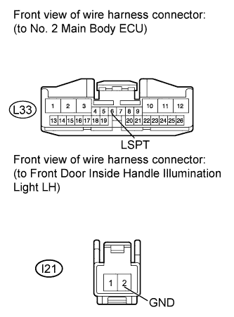
Disconnect the I21 light connector.
-
Measure the voltage according to the value(s) in the table below.
Standard Voltage Tester Connection Condition Specified Condition I21-1 (+B) - Body ground Always 11 to 14 V
NG
REPAIR OR REPLACE HARNESS OR CONNECTOR
OK
-
-
INSPECT FRONT DOOR INSIDE HANDLE ILLUMINATION LIGHT LH

-
Remove the front door inside handle illumination light LH Click here.
-
Apply battery voltage to the inside handle illumination light and check the illumination condition.
OK Measurement Condition Specified Condition Battery positive (+) → Terminal 1 (+B)
Battery negative (-) → Terminal 2 (GND)
Inside handle illumination light on
NG
REPLACE FRONT DOOR INSIDE HANDLE ILLUMINATION LIGHT LH Click here
OK
-
-
CHECK HARNESS AND CONNECTOR (NO. 2 MAIN BODY ECU - FRONT DOOR INSIDE HANDLE ILLUMINATION LIGHT LH)
-
Disconnect the L33 ECU connector.
-
Disconnect the I21 light connector.
-
Measure the resistance according to the value(s) in the table below.
Standard Resistance Tester Connection Condition Specified Condition I21-2 (GND) - L33-6 (LSPT) Always Below 1 Ω I21-2 (GND) - Body ground Always 10 kΩ or higher
NG
REPAIR OR REPLACE HARNESS OR CONNECTOR
OK
REPLACE NO. 2 MAIN BODY ECU Click here
-
-
CHECK HARNESS AND CONNECTOR (FRONT DOOR INSIDE HANDLE ILLUMINATION LIGHT RH - BATTERY)
-
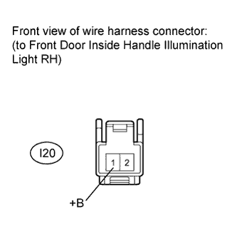
Disconnect the I20 light connector.
-
Measure the voltage according to the value(s) in the table below.
Standard Voltage Tester Connection Condition Specified Condition I20-1 (+B) - Body ground Always 11 to 14 V
NG
REPAIR OR REPLACE HARNESS OR CONNECTOR
OK
-
-
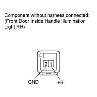
INSPECT FRONT DOOR INSIDE HANDLE ILLUMINATION LIGHT RH
-
Remove the front door inside handle illumination light RH Click here.
-
Apply battery voltage to the inside handle illumination light and check the illumination condition.
OK Measurement Condition Specified Condition Battery positive (+) → Terminal 1 (+B)
Battery negative (-) → Terminal 2 (GND)
Inside handle illumination light on
NG
REPLACE FRONT DOOR INSIDE HANDLE ILLUMINATION LIGHT RH Click here
OK
-
-
CHECK HARNESS AND CONNECTOR (NO. 2 MAIN BODY ECU - FRONT DOOR INSIDE HANDLE ILLUMINATION LIGHT RH)

-
Disconnect the L33 ECU connector.
-
Disconnect the I20 light connector.
-
Measure the resistance according to the value(s) in the table below.
Standard Resistance Tester Connection Condition Specified Condition I20-2 (GND) - L33-6 (LSPT) Always Below 1 Ω I20-2 (GND) - Body ground Always 10 kΩ or higher
NG
REPAIR OR REPLACE HARNESS OR CONNECTOR
OK
REPLACE NO. 2 MAIN BODY ECU Click here
-
-
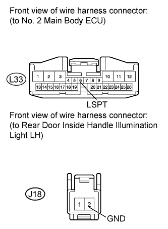
CHECK HARNESS AND CONNECTOR (REAR DOOR INSIDE HANDLE ILLUMINATION LIGHT LH - BATTERY)
-

Disconnect the J18 light connector.
-
Measure the voltage according to the value(s) in the table below.
Standard Voltage Tester Connection Condition Specified Condition J18-1 (+B) - Body ground Always 11 to 14 V
NG
REPAIR OR REPLACE HARNESS OR CONNECTOR
OK
-
-
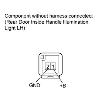
INSPECT REAR DOOR INSIDE HANDLE ILLUMINATION LIGHT LH
-
Remove the rear door inside handle illumination light LH Click here.
-
Apply battery voltage to the inside handle illumination light and check the illumination condition.
OK Measurement Condition Specified Condition Battery positive (+) → Terminal 1 (+B)
Battery negative (-) → Terminal 2 (GND)
Inside handle illumination light on
NG
REPLACE REAR DOOR INSIDE HANDLE ILLUMINATION LIGHT LH Click here
OK
-
-
CHECK HARNESS AND CONNECTOR (NO. 2 MAIN BODY ECU - REAR DOOR INSIDE HANDLE ILLUMINATION LIGHT LH)
-
Disconnect the L33 ECU connector.
-
Disconnect the J18 light connector.
-
Measure the resistance according to the value(s) in the table below.
Standard Resistance Tester Connection Condition Specified Condition J18-2 (GND) - L33-6 (LSPT) Always Below 1 Ω J18-2 (GND) - Body ground Always 10 kΩ or higher
NG
REPAIR OR REPLACE HARNESS OR CONNECTOR
OK
REPLACE NO. 2 MAIN BODY ECU Click here
-
-
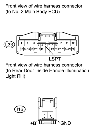
CHECK HARNESS AND CONNECTOR (REAR DOOR INSIDE HANDLE ILLUMINATION LIGHT RH - BATTERY)
-

Disconnect the J16 light connector.
-
Measure the voltage according to the value(s) in the table below.
Standard Voltage Tester Connection Condition Specified Condition J16-1 (+B) - Body ground Always 11 to 14 V
NG
REPAIR OR REPLACE HARNESS OR CONNECTOR
OK
-
-
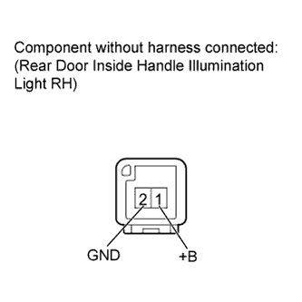
INSPECT REAR DOOR INSIDE HANDLE ILLUMINATION LIGHT RH
-
Remove the rear door inside handle illumination light RH Click here.
-
Apply battery voltage to the inside handle illumination light and check the illumination condition.
OK Measurement Condition Specified Condition Battery positive (+) → Terminal 1 (+B)
Battery negative (-) → Terminal 2 (GND)
Inside handle illumination light on
NG
REPLACE REAR DOOR INSIDE HANDLE ILLUMINATION LIGHT RH Click here
OK
-
-
CHECK WIRE HARNESS AND CONNECTOR (NO. 2 MAIN BODY ECU - REAR DOOR INSIDE HANDLE ILLUMINATION LIGHT RH)
-
Disconnect the L33 ECU connector.
-
Disconnect the J16 light connector.
-
Measure the resistance according to the value(s) in the table below.
Standard Resistance Tester Connection Condition Specified Condition J16-2 (GND) - L33-6 (LSPT) Always Below 1 Ω J16-2 (GND) - Body ground Always 10 kΩ or higher
NG
REPAIR OR REPLACE HARNESS OR CONNECTOR
OK
REPLACE NO. 2 MAIN BODY ECU Click here
-
-
INSPECT FRONT DOOR COURTESY LIGHT SWITCH LH
-
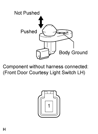
Remove the front door courtesy light switch LH Click here.
-
Measure the resistance according to the value(s) in the table below.
Standard Resistance Tester Connection Switch Condition Specified Condition 1 - Body ground Not pushed Below 1 Ω Pushed 10 kΩ or higher
NG
REPLACE FRONT DOOR COURTESY LIGHT SWITCH LH Click here
OK
-
-
CHECK HARNESS AND CONNECTOR (FRONT DOOR COURTESY LIGHT SWITCH LH - MAIN BODY ECU AND BODY GROUND)
-
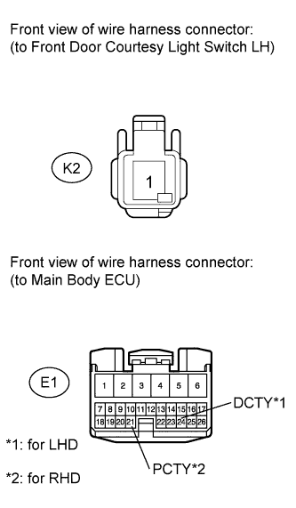
Disconnect the K2 switch connector.
-
Disconnect the E1 ECU connector.
-
Measure the resistance according to the value(s) in the table below.
Standard Resistance for LHD Tester Connection Condition Specified Condition K2-1 - E1-24 (DCTY) Always Below 1 Ω K2-1 - Body ground Always 10 kΩ or higher for RHD Tester Connection Condition Specified Condition K2-1 - E1-21 (PCTY) Always Below 1 Ω K2-1 - Body ground Always 10 kΩ or higher
NG
REPAIR OR REPLACE HARNESS OR CONNECTOR
OK
REPLACE MAIN BODY ECU
-
-
INSPECT FRONT DOOR COURTESY LIGHT SWITCH RH
-
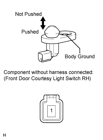
Remove the front door courtesy light switch RH Click here.
-
Measure the resistance according to the value(s) in the table below.
Standard Resistance Tester Connection Switch Condition Specified Condition 1 - Body ground Not pushed Below 1 Ω Pushed 10 kΩ or higher
NG
REPLACE FRONT DOOR COURTESY LIGHT SWITCH RH Click here
OK
-
-
CHECK HARNESS AND CONNECTOR (FRONT DOOR COURTESY LIGHT SWITCH RH - MAIN BODY ECU AND BODY GROUND)
-
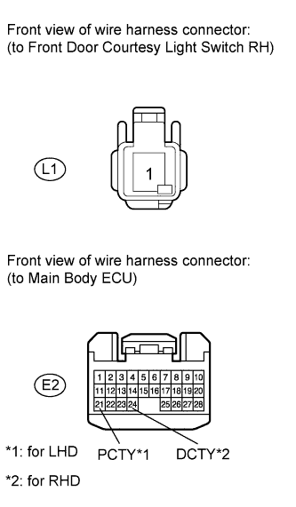
Disconnect the L1 switch connector.
-
Disconnect the E2 ECU connector.
-
Measure the resistance according to the value(s) in the table below.
Standard Resistance for LHD Tester Connection Condition Specified Condition L1-1 - E2-21 (PCTY) Always Below 1 Ω L1-1 - Body ground Always 10 kΩ or higher for RHD Tester Connection Condition Specified Condition L1-1 - E2-24 (DCTY) Always Below 1 Ω L1-1 - Body ground Always 10 kΩ or higher
NG
REPAIR OR REPLACE HARNESS OR CONNECTOR
OK
REPLACE MAIN BODY ECU
-
-
INSPECT REAR DOOR COURTESY LIGHT SWITCH LH
-
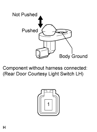
Remove the rear door courtesy light switch LH Click here.
-
Measure the resistance according to the value(s) in the table below.
Standard Resistance Tester Connection Switch Condition Specified Condition 1 - Body ground Not pushed Below 1 Ω Pushed 10 kΩ or higher
NG
REPLACE REAR DOOR COURTESY LIGHT SWITCH LH Click here
OK
-
-
CHECK HARNESS AND CONNECTOR (REAR DOOR COURTESY LIGHT SWITCH LH - MAIN BODY ECU AND BODY GROUND)
-
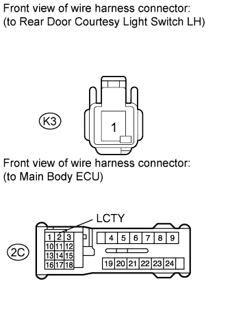
Disconnect the K3 switch connector.
-
Disconnect the 2C ECU connector.
-
Measure the resistance according to the value(s) in the table below.
Standard Resistance Tester Connection Condition Specified Condition K3-1 - 2C-2 (LCTY) Always Below 1 Ω K3-1 - Body ground Always 10 kΩ or higher
NG
REPAIR OR REPLACE HARNESS OR CONNECTOR
OK
REPLACE MAIN BODY ECU
-
-
INSPECT REAR DOOR COURTESY LIGHT SWITCH RH
-
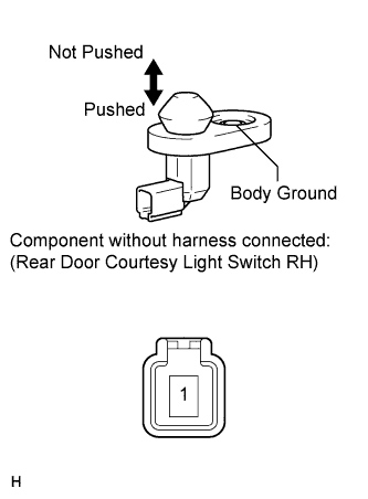
Remove the rear door courtesy light switch RH Click here.
-
Measure the resistance according to the value(s) in the table below.
Standard Resistance Tester Connection Switch Condition Specified Condition 1 - Body ground Not pushed Below 1 Ω Pushed 10 kΩ or higher
NG
REPLACE REAR DOOR COURTESY LIGHT SWITCH RH Click here
OK
-
-
CHECK HARNESS AND CONNECTOR (REAR DOOR COURTESY LIGHT SWITCH RH - MAIN BODY ECU AND BODY GROUND)
-
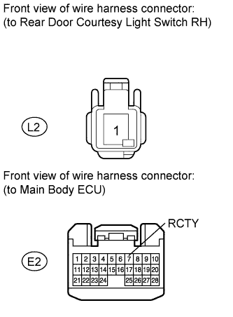
Disconnect the L2 switch connector.
-
Disconnect the E2 ECU connector.
-
Measure the resistance according to the value(s) in the table below.
Standard Resistance Tester Connection Condition Specified Condition L2-1 - E2-7 (RCTY) Always Below 1 Ω L2-1 - Body ground Always 10 kΩ or higher
NG
REPAIR OR REPLACE HARNESS OR CONNECTOR
OK
REPLACE MAIN BODY ECU
-