LIGHTING SYSTEM Personal Light does not Illuminate
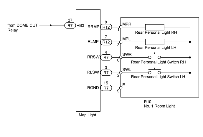
WIRING DIAGRAM
INSPECTION PROCEDURE
PROCEDURE
-
CONFIRM LIGHT POSITION
-
Check the malfunctioning personal light.
Result Result Proceed to Rear personal light A Front personal light B
B 
REPLACE MAP LIGHT Click here
A 
-
-
CHECK HARNESS AND CONNECTOR (MAP LIGHT - BATTERY)
-
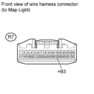
Disconnect the R7 light connector.
-
Measure the voltage to the according to the value(s) in the table below.
Standard Voltage Tester Connection Condition Specified Condition R7-27 (+B3) - Body ground Always 11 to 14 V
NG
REPAIR OR REPLACE HARNESS OR CONNECTOR
OK
-
-
INSPECT NO. 1 ROOM LIGHT
-
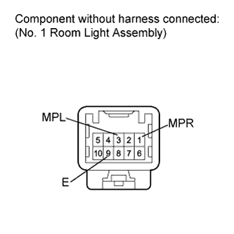
Remove the No. 1 room light connector Click here.
-
Apply battery voltage to the connector, and check the illumination condition.
OK Measurement Condition Specified Condition Battery positive (+) → Terminal 1 (MPR)
Battery negative (-) → Terminal 9 (E)
Illuminates Battery positive (+) → Terminal 3 (MPL)
Battery negative (-) → Terminal 9 (E)
Illuminates
NG
REPLACE ROOM NO. 1 LIGHT Click here
OK
-
-
CHECK HARNESS AND CONNECTOR (MAP LIGHT - NO. 1 ROOM LIGHT)
-
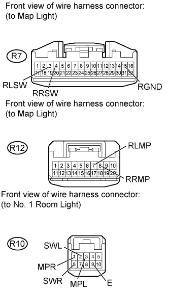
Disconnect the R7, R12 and R10 light connectors.
-
Measure the resistance to the according value(s) in the table below.
Standard Resistance Tester Connection Condition Specified Condition R7-15 (RGND) - R10-9 (E) Always Below 1 Ω R7-3 (RLSW) - R10-2 (SWL) R7-4 (RRSW) - R10-6 (SWR) R12-7 (RLMP) - R10-3 (MPL) R12-8 (RRMP) - R10-1 (MPR) R7-15 (RGND) - Body ground Always 10 kΩ or higher R7-3 (RLSW) - Body ground R7-4 (RRSW) - Body ground R12-7 (RLMP) - Body ground R12-8 (RRMP) - Body ground
NG
REPAIR OR REPLACE HARNESS OR CONNECTOR
OK 
REPLACE MAP LIGHT Click here
-