LIGHTING SYSTEM, Diagnostic DTC:B124E

| DTC Code | DTC Name |
|---|---|
| B124E | Flasher Relay Circuit |
DESCRIPTION
This DTC is stored when the main body ECU detects malfunctions in the turn signal flasher relay circuit.
| DTC Code | DTC Detection Condition | Trouble Area |
|---|---|---|
| B124E | Malfunction in turn signal flasher relay circuit |
|
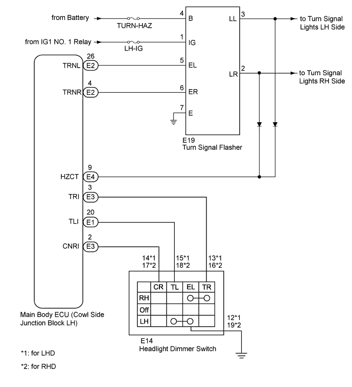
WIRING DIAGRAM
INSPECTION PROCEDURE
Note
Inspect the fuses for circuits related to this system before performing the following inspection procedure.
PROCEDURE
-
CLEAR DTC
-
Clear the DTCs Click here.
NEXT 
-
-
CHECK DTC
-
Operate the turn signal switch to cause the left and right turns signal lights to each blink for 3 seconds or more.
-
Check for DTCs Click here.
OK DTC B124E is not output.
NG 
READ VALUE USING INTELLIGENT TESTER (TURN SIGNAL SWITCH) Click here
OK 
USE SIMULATION METHOD TO CHECK Click here
-
-
READ VALUE USING INTELLIGENT TESTER (TURN SIGNAL SWITCH)
-
Using the intelligent tester, read the Data List Click here.
Main Body Tester Display Measurement Item/Range Normal Condition Diagnostic Note Right LaneChgFlas Turn Signal Switch Turn signal switch (right lane change position) signal / ON or OFF ON: Turn signal switch moved to the right lane change position
OFF: Turn signal switch off
- Left LaneChgFlas Turn Signal Switch Turn signal switch (left lane change position) signal / ON or OFF ON: Turn signal switch moved to the left lane change position
OFF: Turn signal switch off
- R or L TurnFlas Turn Signal Switch (Auto Off) Turn signal switch (left or right) signal / ON or OFF ON: Turn signal switch moved to the left or right position
OFF: Turn signal switch off
- OK When the headlight dimmer switch (turn signal switch) operation is performed, the result will be the same as above.
NG
INSPECT HEADLIGHT DIMMER SWITCH (TURN SIGNAL SWITCH) Click here
OK
-
-
CHECK HARNESS AND CONNECTOR (TURN SIGNAL FLASHER - BATTERY AND BODY GROUND)
-
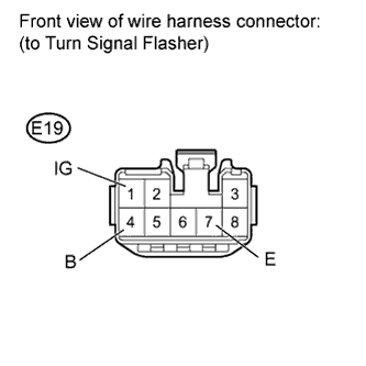
Disconnect the E19 flasher connector.
-
Measure the voltage according to the value(s) in the table below.
Standard Voltage Tester Connection Switch Condition Specified Condition E19-4 (B) - Body ground Always 11 to 14 V E19-1 (IG) - Body ground Engine switch on (IG) 11 to 14 V -
Measure the resistance according to the value(s) in the table below.
Standard Resistance Tester Connection Condition Specified Condition E19-7 (E) - Body ground Always Below 1 Ω
NG 
REPAIR OR REPLACE HARNESS OR CONNECTOR
OK
-
-
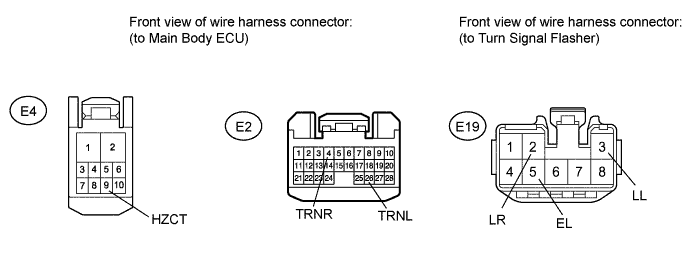
CHECK HARNESS AND CONNECTOR (MAIN BODY ECU - TURN SIGNAL FLASHER)
-
Disconnect the E2 and E4 ECU connectors.
-
Disconnect the E19 flasher connector.
-
Measure the resistance according to the value(s) in the table below.
Standard Resistance Tester Connection Condition Specified Condition E4-9 (HZCT) - E19-3 (LL) Always 1 MΩ or higher*1 Approximately 1 Ω*2 E4-9 (HZCT) - E19-2 (LR) Always 1 MΩ or higher*1 Approximately 1 Ω*2 E2-26 (TRNL) - E19-5 (EL) Always Below 1 Ω E2-4 (TRNR) - E19-6 (ER) Always Below 1 Ω E2-26 (TRNL) - Body ground Always 10 kΩ or higher E2-4 (TRNR) - Body ground Always 10 kΩ or higher Tech Tips
*1: Measure the resistance by connecting the positive (+) tester probe to terminal E4-9 (HZCT) and the negative (-) tester probe to terminal E19-3 (LL) or E19-2 (LR).
*2: Measure the resistance by connecting the positive (+) tester probe to terminal E19-3 (LL) or E19-2 (LR) and the negative (-) tester probe to terminal E4-9 (HZCT). Use this value only as a reference, as the resistance varies depending on the measurement instrument.
NG
REPAIR OR REPLACE HARNESS OR CONNECTOR
OK
-
-
CHECK TURN SIGNAL FLASHER
-
for LHD:
-
Temporarily replace the turn signal flasher with a new or normally functioning one Click here.
-
-
for RHD:
-
Temporarily replace the turn signal flasher with a new or normally functioning one Click here.
-
-
Operate the turn signal switch to cause the left and right turns signal lights to each blink for 3 seconds or more.
-
Check for DTCs Click here.
OK DTC B124E is not output.
NG
REPLACE MAIN BODY ECU
OK
END (TURN SIGNAL FLASHER WAS DEFECTIVE)
-
-
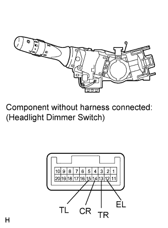
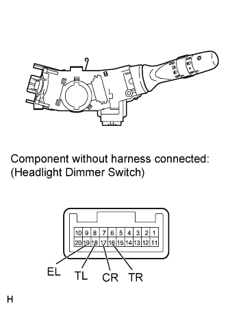
INSPECT HEADLIGHT DIMMER SWITCH (TURN SIGNAL SWITCH)
-
for LHD:
-
Remove the headlight dimmer switch Click here.
-
Measure the resistance according to the value(s) in the table below.
Standard Resistance Tester Connection Switch Condition Specified Condition 13 (TR) - 12 (EL) Turn signal switch right turn Below 1 Ω Turn signal switch off 10 kΩ or higher 14 (CR) - 12 (EL) Turn signal switch right turn Below 1 Ω Turn signal switch left turn Below 1 Ω Turn signal switch off 10 kΩ or higher 15 (TL) - 12 (EL) Turn signal switch left turn Below 1 Ω Turn signal switch off 10 kΩ or higher
-
-
fro RHD:
-
Remove the headlight dimmer switch Click here.
-
Measure the resistance according to the value(s) in the table below.
Standard Resistance Tester Connection Switch Condition Specified Condition 16 (TR) - 19 (EL) Turn signal switch right turn Below 1 Ω Turn signal switch off 10 kΩ or higher 17 (CR) - 19 (EL) Turn signal switch right turn Below 1 Ω Turn signal switch left turn Below 1 Ω Turn signal switch off 10 kΩ or higher 18 (TL) - 19 (EL) Turn signal switch left turn Below 1 Ω Turn signal switch off 10 kΩ or higher Result Result Proceed to OK A NG (for LHD) B NG (for RHD) C
-
B
REPLACE HEADLIGHT DIMMER SWITCH Click here
C
REPLACE HEADLIGHT DIMMER SWITCH Click here
A
-
-
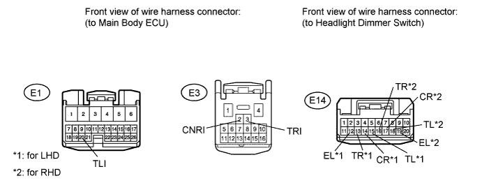
CHECK HARNESS AND CONNECTOR (HEADLIGHT DIMMER SWITCH - MAIN BODY ECU AND BODY GROUND)
-
Disconnect the E14 switch connector.
-
Disconnect the E1 and E3 ECU connectors.
-
Measure the resistance according to the value(s) in the table below.
Standard Resistance for LHD Tester Connection Condition Specified Condition E3-3 (TRI) - E14-13 (TR) Always Below 1 Ω E1-20 (TLI) - E14-15 (TL) Always Below 1 Ω E3-2 (CNRI) - E14-14 (CR) Always Below 1 Ω E14-12 (EL) - Body ground Always Below 1 Ω E3-3 (TRI) - Body ground Always 10 kΩ or higher E1-20 (TLI) - Body ground Always 10 kΩ or higher E3-2 (CNRI) - Body ground Always 10 kΩ or higher for RHD Tester Connection Condition Specified Condition E3-3 (TRI) - E14-16 (TR) Always Below 1 Ω E1-20 (TLI) - E14-18 (TL) Always Below 1 Ω E3-2 (CNRI) - E14-17 (CR) Always Below 1 Ω E14-19 (EL) - Body ground Always Below 1 Ω E3-3 (TRI) - Body ground Always 10 kΩ or higher E1-20 (TLI) - Body ground Always 10 kΩ or higher E3-2 (CNRI) - Body ground Always 10 kΩ or higher
NG
REPAIR OR REPLACE HARNESS OR CONNECTOR
OK
REPLACE MAIN BODY ECU
-