LIGHTING SYSTEM, Diagnostic DTC:B1244

| DTC Code | DTC Name |
|---|---|
| B1244 | Light Sensor Circuit Malfunction |
DESCRIPTION
This DTC is stored when a failure of the automatic light control sensor circuit is detected.
| DTC Code | DTC Detection Condition | Trouble Area |
|---|---|---|
| B1244 | When either condition below is met:
|
|
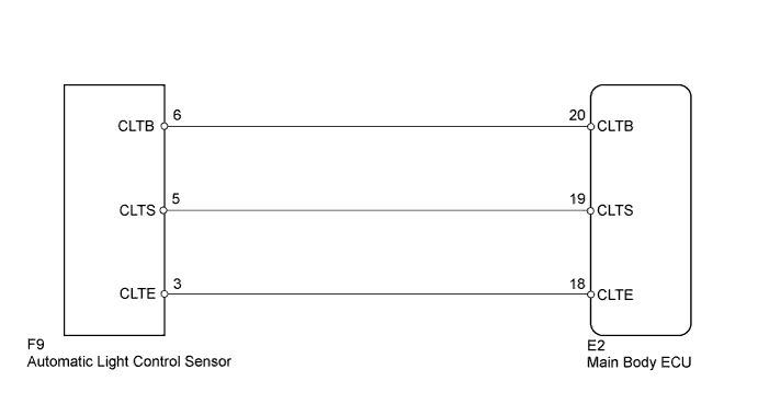
WIRING DIAGRAM
INSPECTION PROCEDURE
PROCEDURE
-
CHECK FOR DTC
-
Clear the DTCs Click here.
-
Check for DTCs Click here.
OK DTC B1244 output does not occur.
NG 
READ VALUE USING INTELLIGENT TESTER (AUTOMATIC LIGHT CONTROL SENSOR) Click here
OK 
USE SIMULATION METHOD TO CHECK Click here
-
-
READ VALUE USING INTELLIGENT TESTER (AUTOMATIC LIGHT CONTROL SENSOR)
-
Using the intelligent tester, read the Data List.
Main Body Tester Display Measurement Item/Range Normal Condition Diagnostic Note Illumination Rate Info Illuminance detected by automatic light control sensor/0 to 235600 lx Illuminance value displayed - OK Illuminance value is displayed normally.
NG
CHECK MAIN BODY ECU (CLTB - CLTE VOLTAGE) Click here
OK
REPLACE MAIN BODY ECU
-
-
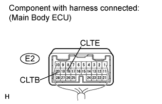
CHECK MAIN BODY ECU (CLTB - CLTE VOLTAGE)
-
Measure the voltage according to the value(s) in the table below.
Standard Voltage Tester Connection Switch Condition Specified Condition E2-20 (CLTB) - E2-18 (CLTE) Engine switch on (IG) 11 to 14 V
NG 
REPLACE MAIN BODY ECU
OK 
-
-
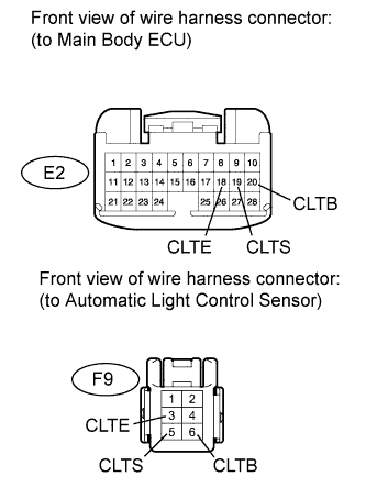
CHECK HARNESS AND CONNECTOR (MAIN BODY ECU - AUTOMATIC LIGHT CONTROL SENSOR)
-
Disconnect the E2 ECU connector.
-
Disconnect the F9 sensor connector.
-
Measure the resistance according to the value(s) in the table below.
Standard Resistance Tester Connection Condition Specified Condition E2-20 (CLTB) - F9-6 (CLTB) Always Below 1 Ω E2-19 (CLTS) - F9-5 (CLTS) E2-18 (CLTE) - F9-3 (CLTE) E2-20 (CLTB) - Body ground Always 10 kΩ or higher E2-19 (CLTS) - Body ground E2-18 (CLTE) - Body ground
NG
REPAIR OR REPLACE HARNESS OR CONNECTOR
OK
REPLACE AUTOMATIC LIGHT CONTROL SENSOR Click here
-