LIGHTING SYSTEM TERMINALS OF ECU

-
CHECK AFS ECU (HEADLIGHT SWIVEL ECU)
-
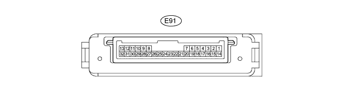
Disconnect the E91 ECU connector.
-
Measure the voltage and resistance according to the value(s) in the table below.
Terminal No. (Symbol) Wiring Color Terminal Description Condition Specified Condition E91-14 (IGS) - E91-22 (E1) R - W-B IG power supply Engine switch on (IG) 11 to 14 V Engine switch off Below 1 V E91-15 (IG) - E91-22 (E1) L - W-B IG power supply Engine switch on (IG) 11 to 14 V Engine switch off Below 1 V E91-22 (E1) - Body ground W-B - Body ground Ground Always Below 1 Ω
-
If the result is not as specified, there may be a malfunction on the wire harness side.
-
-
Reconnect the E91 ECU connector.
-
Measure the voltage and resistance according to the value(s) in the table below.
Terminal No. (Symbol) Wiring Color Terminal Description Condition Specified Condition E91-1 (SMBL) - E91-22 (E1) R - W-B Headlight swivel motor LH power output Engine switch on (IG) 11 to 14 V E91-2 (SMBR) - E91-22 (E1) R - W-B Headlight swivel motor RH power output Engine switch on (IG) 11 to 14 V E91-10 (SMR) - E91-22 (E1) L - W-B Headlight swivel motor RH Engine switch on (IG) Pulse generation E91-11 (RH+) - E91-22 (E1) P - W-B Headlight swivel motor RH (leveling portion) Engine switch on (IG) Pulse generation E91-12 (MPX1) - E91-22 (E1) LG - W-B CAN communication Engine switch on (IG) Pulse generation E91-13 (MPX2) - E91-22 (E1) B - W-B CAN communication Engine switch on (IG) Pulse generation E91-17 (SHFL) - E91-22 (E1) GR - W-B Vehicle height signal Engine switch on (IG) (no passengers, no luggage, vehicle not moving) 2.20 to 2.80 V E91-18 (SBR) - E91-22 (E1) L - W-B Vehicle height signal Engine switch on (IG) 4.5 to 5.5 V E91-19 (SHRL) - E91-22 (E1) SB - W-B Vehicle height signal Engine switch on (IG) (no passengers, no luggage, vehicle not moving) 2.21 to 2.80 V E91-21 (SGR) - E91-22 (E1) P - W-B Vehicle height signal Always Below 1 Ω E91-23 (SMGL) - E91-22 (E1) B - W-B Headlight swivel motor LH Always Below 1 Ω E91-24 (SMGR) - E91-22 (E1) B - W-B Headlight swivel motor RH Always Below 1 Ω E91-29 (SML) - E91-22 (E1) V - W-B Headlight swivel motor LH Engine switch on (IG) Pulse generation E91-30 (LH+) - E91-22 (E1) G - W-B Headlight swivel motor LH (leveling portion) Engine switch on (IG) Pulse generation E91-32 (MSW) - E91-22 (E1) W - W-B AFS OFF switch signal Engine switch on (IG), headlight AFS OFF switch on Below 1 V Engine switch on (IG), headlight AFS OFF switch off 11 to 14 V
-
-
CHECK MAIN BODY ECU (COWL SIDE JUNCTION BLOCK LH)
-
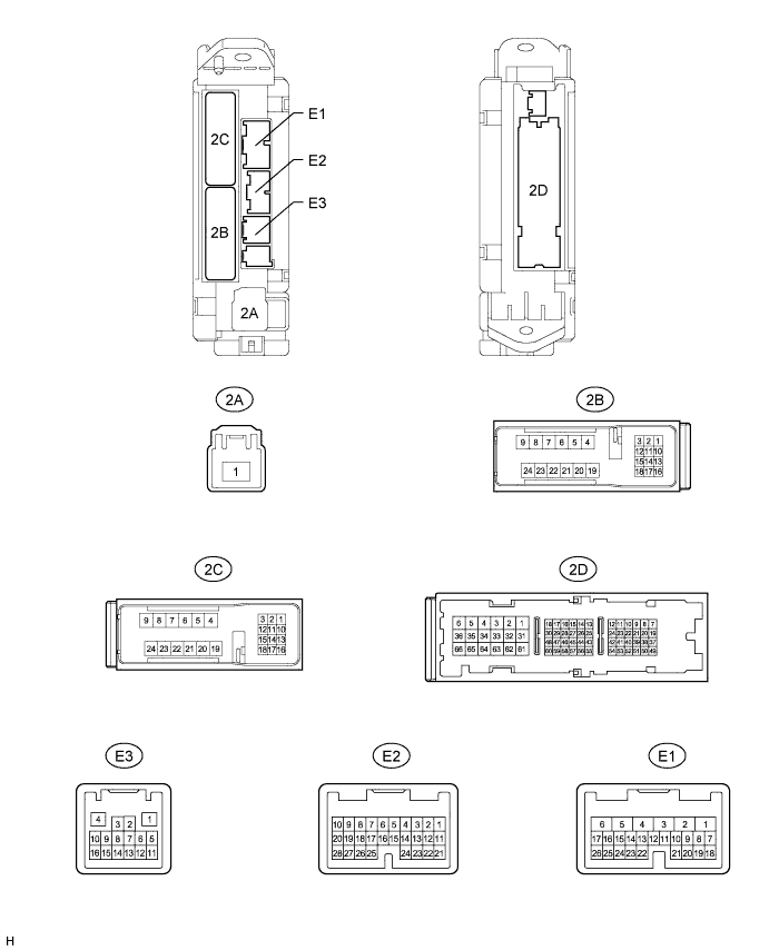
Disconnect the 2A, 2B, 2C, 2D, E1, E2, and E3 ECU connectors.
-
Measure the voltage and resistance according to the value(s) in the table below.
Terminal No. (Symbol) Wiring Color Terminal Description Condition Specified Condition 2A-1 - Body ground B - Body ground Battery power supply Always 11 to 14 V 2A-1 (TRLY) - Body ground B - Body ground Taillight power supply Always 11 to 14 V 2D-62 (GND2) - Body ground W-B - Body ground Body ground Always Below 1 Ω E3-1 (GND3) - Body ground BR - Body ground Body ground Always Below 1 Ω E1-24 (DCTY) - Body ground*1 L - Body ground Front door courtesy light switch LH signal Front door LH open Below 1 Ω Engine switch off, and front door LH closed 10 kΩ or higher E1-24 (DCTY) - Body ground*2 P - Body ground Front door courtesy light switch RH signal Front door RH open Below 1 Ω Engine switch off, and front door RH closed 10 kΩ or higher E2-21 (PCTY) - Body ground*1 P - Body ground Front door courtesy light switch RH signal Front door RH open Below 1 Ω Engine switch off, and front door RH closed 10 kΩ or higher E2-21 (PCTY) - Body ground*2 L - Body ground Front door courtesy light switch LH signal Front door LH open Below 1 Ω Engine switch off, and front door LH closed 10 kΩ or higher 2C-2 (LCTY) - Body ground W - Body ground Rear door courtesy light switch LH signal Rear door LH open Below 1 Ω Engine switch off, and rear door LH closed 10 kΩ or higher E2-7 (RCTY) - Body ground G - Body ground Rear door courtesy light switch RH signal Rear door RH open Below 1 Ω Engine switch off, and rear door RH closed 10 kΩ or higher E2-25 (BCTY) - Body ground W - Body ground Back door courtesy light switch signal Back door open Below 1 Ω Engine switch off, and back door closed 10 kΩ or higher E1-23 (TAIL) - Body ground V - Body ground Light control switch TAIL signal Light control switch tail Below 1 Ω Light control switch except tail 10 kΩ or higher E2-17 (HEAD) - Body ground R - Body ground Light control switch HEAD signal Light control switch head Below 1 Ω Light control switch off 10 kΩ or higher E1-21 (A) - Body ground G - Body ground Light control switch AUTO signal Light control switch AUTO Below 1 Ω Light control switch off 10 kΩ or higher 2D-13 (HU) - Body ground R - Body ground Dimmer switch high signal Dimmer switch high Below 1 Ω Dimmer switch high 10 kΩ or higher E1-13 (HF) - Body ground GR - Body ground Dimmer switch flash signal Dimmer switch flash Below 1 Ω Dimmer switch flash 10 kΩ or higher E2-28 (FFOG) - Body ground R - Body ground Front fog light switch signal Front fog light switch on Below 1 Ω Front fog light switch off 10 kΩ or higher E2-9 (RFOG) - Body ground*3 R - Body ground Rear fog light switch signal Rear fog light switch on Below 1 Ω Rear fog light switch off 10 kΩ or higher 2B-22 (STP) - Body ground R - Body ground Stop light switch signal Brake pedal depressed Below 1 Ω Brake pedal released 10 kΩ or higher E3-11 (FSPT) - Body ground L - Body ground Interior foot light signal Engine switch on (IG), and door open Below 1 Ω Engine switch on (IG), and door closed 10 kΩ or higher
-
*1: for LHD
-
*2: for RHD
-
*3: w/ Rear Fog Light
-
If the result is not as specified, there may be a malfunction on the wire harness side.
-
-
Reconnect the 2A, 2B, 2C, 2D, E1, E2, and E3 ECU connectors.
-
Measure the voltage according to the value(s) in the table below.
Terminal No. (Symbol) Wiring Color Terminal Description Condition Specified Condition E2-4 (TRNR) - Body ground B - Body ground RH side turn signal Headlight dimmer switch (TURN R) off 11 to 14 V Headlight dimmer switch (TURN R) on Below 1 V E2-8 (DRLE) - Body ground R - Body ground Daytime running light circuit Daytime running light on Below 1 V Daytime running light off 11 to 14 V E2-15 (DIM) - Body ground L - Body ground Hi-beam circuit Light control switch head, dimmer switch high Below 1 V Light control switch head, dimmer switch except high 11 to 14 V E1-20 (TLI) - Body ground GR - Body ground LH side turn signal switch signal Headlight dimmer switch (TURN L) off 11 to 14 V Headlight dimmer switch (TURN L) on Below 1 V E3-2 (CNRI) - Body ground LG - Body ground LH or RH side turn signal switch signal Headlight dimmer switch (TURN) off 11 to 14 V Headlight dimmer switch (TURN L or R) on Below 1 V E3-3 (TRI) - Body ground SB - Body ground RH side turn signal switch signal Headlight dimmer switch (TURN R) off 11 to 14 V Headlight dimmer switch (TURN R) on Below 1 V E4-9 (HZCT) - Body ground W - Body ground Turn signal light control signal Turn signal lights blinks Below 1 V ←→ 11 to 14 V E2-26 (TRNL) - Body ground L - Body ground LH side turn signal Headlight dimmer switch (TURN L) off 11 to 14 V Headlight dimmer switch (TURN L) on Below 1 V 2B-18 (HRLY) - Body ground L - Body ground Lo-beam circuit Light control switch head, dimmer switch low Below 1 V Light control switch head, dimmer switch except low 11 to 14 V 2D-39 (DOMR) - Body ground W - Body ground Battery save system (interior light auto cut function) signal Battery save system (interior light auto cut function) operating 11 to 14 V Battery save system (interior light auto cut function) not operating Below 1 V E1-4 (FFGO) - Body ground R - Body ground Fog light circuit Light control switch tail, front fog light switch on Below 1 V Light control switch tail, front fog light switch off 11 to 14 V E3-14 (RFGO) - Body ground* R - Body ground Rear fog light circuit Light control switch tail, rear fog light switch on Below 1 V Light control switch tail, rear fog light switch off 11 to 14 V
-
*: w/ Rear Fog Light
-
If the result is not as specified, the ECU may have a malfunction.
-
-
-
CHECK INNER REAR VIEW MIRROR ASSEMBLY

-
Disconnect the R13 mirror connector.
-
Measure the voltage and resistance according to the value(s) in the table below.
Terminal No. (Symbol) Wiring Color Terminal Description Condition Specified Condition R13-1 (IG) - Body ground G - Body ground IG power supply Engine switch on (IG) 11 to 14 V Engine switch off Below 1 V R13-2 (E) - Body ground W-B - Body ground Inner rear view mirror ground Always Below 1 Ω -
Reconnect the R13 mirror connector.
-
Measure the voltage according to the value(s) in the table below.
Terminal No. (Symbol) Wiring Color Terminal Description Condition Specified Condition R13-10 (LIN) - R13-2 (E) B - W-B LIN communication Automatic high beam system operates Pulse generation
(See waveform 1)
If the result is not as specified, the inner rear view mirror assembly may have a malfunction.
-
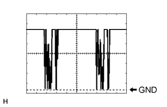
Waveform 1
Item Content Terminal No. (Symbol) R13-10 (LIN) - R13-2 (E) Tool setting 2 V/DIV., 20 ms./DIV. Condition Automatic high beam system operates
-
-
-
CHECK NO. 2 MAIN BODY ECU
-
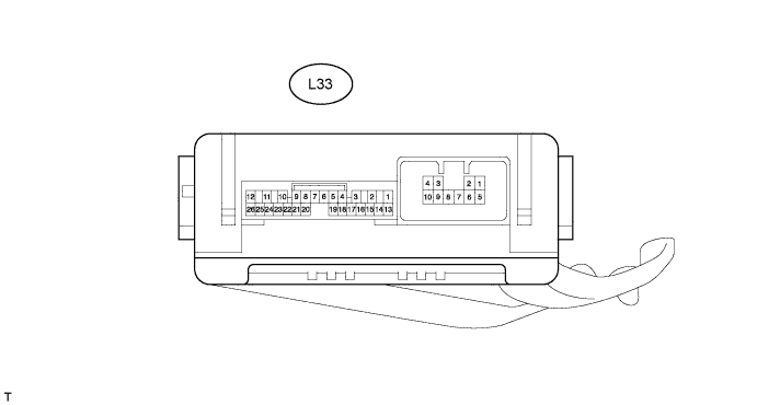
Disconnect the L33 ECU connector.
-
Measure the voltage according to the value(s) in the table below.
Terminal No. (Symbol) Wiring Color Terminal Description Condition Specified Condition L33-14 (BECU) - Body ground R - Body ground B power supply Always 11 to 14 V L33-13 (SIG) - Body ground G - Body ground SIG power supply Engine switch on (IG) 11 to 14 V L33-13 (SIG) - Body ground G - Body ground SIG power supply Engine switch off Below 1 V L33-6 (LSPT) - Body ground L - Body ground Inside handle illumination signal Engine switch on (IG), and door opened 11 to 14 V Engine switch on (IG), and door closed Below 1 V L33-9 (RBD1) - Body ground L - Body ground Side step light LH signal Front door LH open 11 to 14 V Front door LH closed Below 1 V L33-21 (RBD2) - Body ground L - Body ground Side step light RH signal Front door RH open 11 to 14 V Front door RH closed Below 1 V
-
If the result is not as specified, there may be a malfunction on the wire harness side.
-
-
-
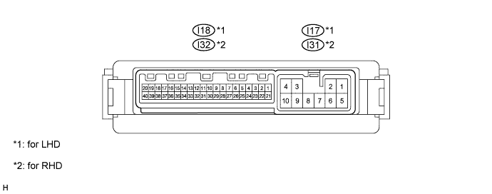
CHECK OUTER MIRROR CONTROL ECU
-
for LHD:
-
Disconnect the I17 ECU connector.
-
Measure the voltage and resistance according to the value(s) in the table below.
Terminal No.
(Symbol)
Wiring Color Terminal Description Condition Specified Condition I17-9 (GND) - Body ground W-B - Body ground Ground Always Below 1 Ω I17-3 (B) - I17-9 (GND) R - W-B Battery (ECU power source) Always 11 to 14 V I17-4 (ACC) - I17-9 (GND) GR - W-B ACC power supply Engine switch off Below 2 V Engine switch on (ACC) 6 V or higher If the result is not as specified, there may be a malfunction on the wire harness side.
-
Reconnect the I17 ECU connector.
-
Measure the voltage according to the value(s) in the table below.
Terminal No.
(Symbol)
Wiring Color Terminal Description Condition Specified Condition I18-17 (LP) - I17-9 (GND) P - W-B Outer rear view mirror LH signal Engine switch on (IG) and front door LH open 9 to 14 V Engine switch off and front door LH closed Below 1 V I18-37 (LP) - I17-9 (GND) P - W-B Outer rear view mirror RH signal Engine switch on (IG) and front door RH open 9 to 14 V Engine switch off and front door RH closed Below 1 V If the result is not as specified, the ECU may have a malfunction.
-
-
for RHD:
-
Disconnect the I31 ECU connector.
-
Measure the voltage and resistance according to the value(s) in the table below.
Terminal No.
(Symbol)
Wiring Color Terminal Description Condition Specified Condition I31-9 (GND) - Body ground W-B - Body ground Ground Always Below 1 Ω I31-3 (B) - I31-9 (GND) R - W-B Battery (ECU power source) Always 11 to 14 V I31-4 (ACC) - I31-9 (GND) GR - W-B ACC power supply Engine switch off Below 2 V Engine switch on (ACC) 6 V or higher If the result is not as specified, there may be a malfunction on the wire harness side.
-
Reconnect the I31 ECU connector.
-
Measure the voltage according to the value(s) in the table below.
Terminal No.
(Symbol)
Wiring Color Terminal Description Condition Specified Condition I32-17 (LP) - I31-9 (GND) P - W-B Outer rear view mirror LH signal Engine switch on (IG) and front door LH open 9 to 14 V Engine switch off and front door LH closed Below 1 V I32-37 (LP) - I31-9 (GND) P - W-B Outer rear view mirror RH signal Engine switch on (IG) and front door RH open 9 to 14 V Engine switch off and front door RH closed Below 1 V If the result is not as specified, the ECU may have a malfunction.
-
-
-
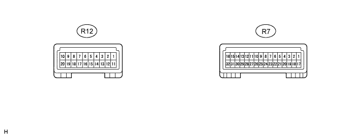
CHECK MAP LIGHT ASSEMBLY
-
Disconnect the R7 and R12 light connectors.
-
Measure the resistance according to the value(s) in the table below.
Terminal No. (Symbol) Wiring Color Terminal Description Condition Specified Condition R12-17 (GND7) - Body ground W-B - Body ground Ground Always Below 1 Ω R12-20 (GND5) - Body ground W-B - Body ground Ground Always Below 1 Ω If the result is not as specified, there may be a malfunction on the wire harness side
-
Reconnect the R7 and R12 light connectors.
-
Measure the voltage according to the value(s) in the table below.
Terminal No. (Symbol) Wiring Color Terminal Description Condition Specified Condition R7-3 (RLSW) - Body ground V - Body ground Rear spot light switch LH signal Rear spot light switch LH off Below 1 V Rear spot light switch LH on 11 to 14 V R7-4 (RRSW) - Body ground Y - Body ground Rear spot light switch RH signal Rear spot light switch RH off Below 1 V Rear spot light switch RH off 11 to 14 V R7-11 (ILLB) - Body ground R - Body ground ACC power supply Engine switch on (ACC) 11 to 14 V R7-15 (RGND) - Body ground W-B - Body ground Ground Always Below 1 Ω R7-27 (+B3) - Body ground R - Body ground Battery power supply Always 11 to 14 V R12-2 (LIN) - Body ground B - Body ground LIN communication Engine switch on (IG) Pulse generation R12-7 (RLMP) - Body ground L - Body ground Rear spot light LH circuit Always 11 to 14 V R12-8 (RRMP) - Body ground G - Body ground Rear spot light RH circuit Always 11 to 14 V R12-11 (GILL) - R12-13 (ILL) G - W illumination circuit
-
Engine switch on (ACC)
-
Headlight dimmer switch off
Below 1 V
-
Engine switch on (ACC)
-
Headlight dimmer switch TAIL
11 to 14 V R12-14 (RRVT) - R12-20 (GND5) G - W-B Back door light signal Back door close Below 1 V Back door open 11 to 14 V R12-18 (RILL) - R12-20 (GND5) G - W-B Rear dome light circuit Rear dome light off 11 to 14 V Rear dome light on Below 1 V If the result is not as specified, there may be a malfunction on the wire harness side
-
-