WIPER AND WASHER SYSTEM Washer Motor Circuit
DESCRIPTION
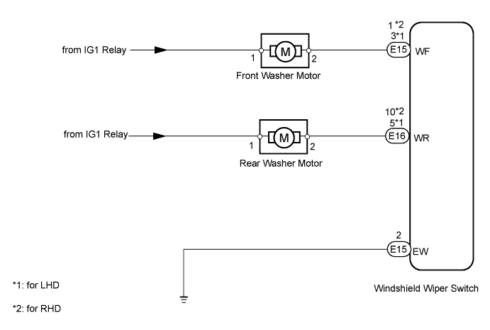
The windshield wiper ECU receives washer switch information from the front wiper switch, and operates the washer motor.
WIRING DIAGRAM
INSPECTION PROCEDURE
PROCEDURE
-
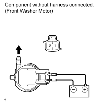
INSPECT FRONT WASHER MOTOR
-
Remove the front washer motor Click here.
-
Apply battery voltage to the windshield washer motor connector and check the operation of the windshield washer motor.
OK Measurement Condition Specified Condition Battery positive (+) → Terminal 1
Battery negative (-) → Terminal 2
Front washer motor operation is normal
NG 
REPLACE FRONT WASHER MOTOR Click here
OK 
-
-
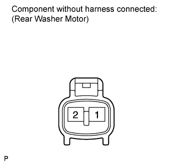
INSPECT REAR WASHER MOTOR
-
Remove the rear washer motor Click here.
-
Apply battery voltage to the windshield washer motor connector and check the operation of the windshield washer motor.
OK Measurement Condition Specified Condition Battery positive (+) → Terminal 1
Battery negative (-) → Terminal 2
Rear washer motor operation is normal
NG
REPLACE REAR WASHER MOTOR Click here
OK
-
-
CHECK HARNESS AND CONNECTOR (FRONT WASHER MOTOR - BODY GROUND)
-
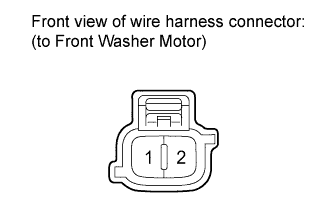
Disconnect the front washer motor connector.
-
Measure the voltage according to the value(s) in the table below.
Standard Voltage Tester Connection Switch Condition Specified Condition 1 - Body ground Engine switch on (IG) 11 to 14 V
NG
REPAIR OR REPLACE HARNESS OR CONNECTOR
OK
-
-
CHECK HARNESS AND CONNECTOR (REAR WASHER MOTOR - BODY GROUND)
-
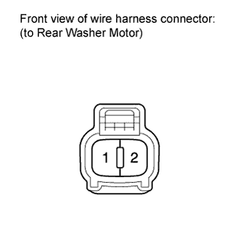
Disconnect the rear washer motor connector.
-
Measure the voltage according to the value(s) in the table below.
Standard Voltage Tester Connection Switch Condition Specified Condition 1 - Body ground Engine switch on (IG) 11 to 14 V
NG
REPAIR OR REPLACE HARNESS OR CONNECTOR
OK
-
-
CHECK HARNESS AND CONNECTOR (WINDSHIELD WIPER SWITCH - BODY GROUND)
-
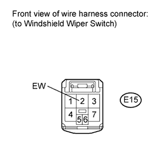
Disconnect the E15 windshield wiper switch connector.
-
Measure the resistance according to the value(s) in the table below.
Standard Resistance Tester Connection Condition Specified Condition E15-2 (EW) - Body ground Always Below 1 Ω
NG
REPAIR OR REPLACE HARNESS OR CONNECTOR
OK
-
-
CHECK HARNESS AND CONNECTOR (FRONT WASHER MOTOR - WINDSHIELD WIPER SWITCH)
-
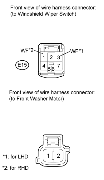
Disconnect the E15 windshield wiper switch connector.
-
Disconnect the washer motor connector.
-
Measure the resistance according to the value(s) in the table below.
Standard Resistance for LHD Tester Connection Condition Specified Condition 2 - E15-3 (WF) Always Below 1 Ω 2 - Body ground Always 10 kΩ or higher for RHD Tester Connection Condition Specified Condition 2 - E15-1 (WF) Always Below 1 Ω 2 - Body ground Always 10 kΩ or higher
NG
REPAIR OR REPLACE HARNESS OR CONNECTOR
OK
-
-
CHECK HARNESS AND CONNECTOR (REAR WASHER MOTOR - WINDSHIELD WIPER SWITCH)
-
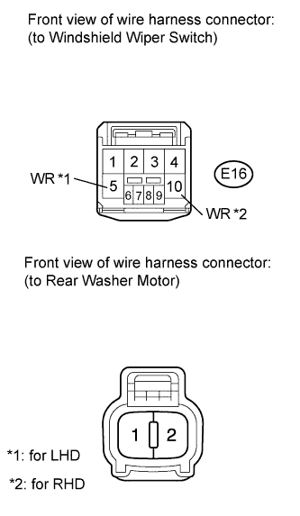
Disconnect the E16 windshield wiper switch connector.
-
Disconnect the washer motor connector.
-
Measure the resistance according to the value(s) in the table below.
Standard Resistance for LHD Tester Connection Condition Specified Condition 2 - E16-5 (WR) Always Below 1 Ω 2 - Body ground Always 10 kΩ or higher for RHD Tester Connection Condition Specified Condition 2 - E16-10 (WR) Always Below 1 Ω 2 - Body ground Always 10 kΩ or higher
NG
REPAIR OR REPLACE HARNESS OR CONNECTOR
OK 
REPLACE WINDSHIELD WIPER SWITCH Click here
-