WIPER AND WASHER SYSTEM Headlight Cleaner Motor and Relay Circuit
DESCRIPTION
This circuit provides power to the headlight cleaner control relay.
The headlight cleaner control relay sends the signal from the switch, etc. to the headlight cleaner motor to operate the headlight cleaner system.
WIRING DIAGRAM
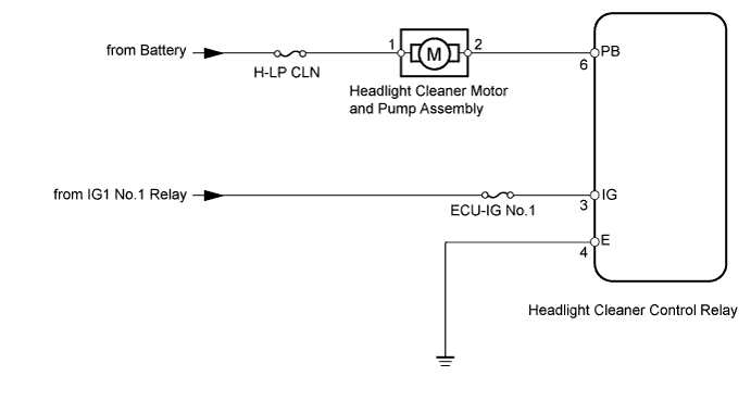
INSPECTION PROCEDURE
PROCEDURE
-
INSPECT FUSE (ECU-IG No.1, H-LP CLN)
-
Remove the ECU-IG No.1 fuse from the cowl side junction block LH.
-
Remove the H-LP CLN H-fuse from the engine room relay block.
-
Measure the resistance according to the value(s) in the table below.
Standard Resistance Tester Connection Condition Specified Condition ECU-IG No. 1 fuse Always Below 1 Ω H-LP CLR H-fuse
NG 
REPLACE FUSE
OK 
-
-
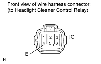
CHECK HARNESS AND CONNECTOR (HEADLIGHT CLEANER CONTROL RELAY - BATTERY AND BODY GROUND)
-
Disconnect the relay connector.
-
Measure the voltage according to the value(s) in the table below.
Standard Voltage Tester Connection Switch Condition Specified Condition 3 (IG) - Body ground Engine switch on (IG) 11 to 14 V 3 (IG) - Body ground Engine switch off Below 1 V -
Measure the resistance according to the value(s) in the table below.
Standard Resistance Tester Connection Condition Specified Condition 4 (E) - Body ground Always Below 1 Ω
NG
REPAIR OR REPLACE HARNESS OR CONNECTOR
OK
-
-
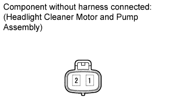
INSPECT HEADLIGHT CLEANER MOTOR AND PUMP ASSEMBLY
-
Remove the headlight cleaner motor Click here.
-
Apply battery voltage to the headlight cleaner motor connector and check the operation of the headlight cleaner motor.
OK Measurement Condition Specified Condition Battery positive (+) → Terminal 1
Battery negative (-) → Terminal 2
Headlight cleaner motor operation is normal
NG
REPLACE HEADLIGHT CLEANER MOTOR AND PUMP ASSEMBLY Click here
OK
-
-
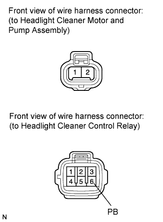
CHECK HARNESS AND CONNECTOR (CLEANER MOTOR - CONTROL RELAY AND BATTERY)
-
Disconnect the cleaner motor connector.
-
Disconnect the control relay connector.
-
Measure the voltage according to the value(s) in the table below.
Standard Voltage Tester Connection Condition Specified Condition 1 - Body ground Always 11 to 14 V -
Measure the resistance according to the value(s) in the table below.
Standard Resistance Tester Connection Condition Specified Condition 2 - 6 (PB) Always Below 1 Ω 2 - Body ground Always 10 kΩ or higher
NG
REPAIR OR REPLACE HARNESS OR CONNECTOR
OK 
PROCEED TO NEXT SUSPECTED AREA SHOWN IN PROBLEM SYMPTOMS TABLE Click here
-