WIPER AND WASHER SYSTEM Headlight Cleaner Switch Circuit
DESCRIPTION
This circuit detects the conditions of the headlight cleaner switch.
-
Headlight cleaner switch signal
-
Headlight operating signal
-
Daytime running light operating signal
-
Front washer motor operating signal
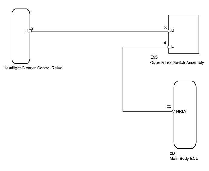
WIRING DIAGRAM
INSPECTION PROCEDURE
PROCEDURE
-
CHECK HEADLIGHT ASSEMBLY (LO BEAM)
-
Check that the headlights illuminate in LO beam.
OK Headlights illuminate in LO beam
NG 
GO TO LIGHTING SYSTEM Click here
OK 
-
-
INSPECT OUTER MIRROR SWITCH ASSEMBLY
-
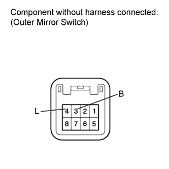
Disconnect the E95 switch connector.
-
Measure the resistance according to the value(s) in the table below.
Standard Resistance Tester Connection Switch Condition Specified Condition 3 (B) - 4 (L) Headlight cleaner switch off 10 kΩ or higher 3 (B) - 4 (L) Headlight cleaner switch on Below 1 Ω
NG
REPLACE OUTER MIRROR SWITCH ASSEMBLY Click here
OK
-
-
CHECK HARNESS AND CONNECTOR (OUTER MIRROR SWITCH - HEADLIGHT CLEANER CONTROL RELAY AND MAIN BODY ECU)
-
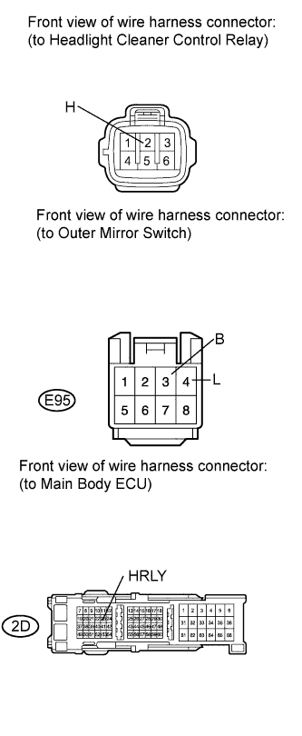
Disconnect the relay connector.
-
Disconnect the E95 switch connector.
-
Disconnect the 2D main body ECU connector.
-
Measure the resistance according to the value(s) in the table below.
Standard Resistance Tester Connection Condition Specified Condition 2 (H) - E95-3 (B) Always Below 1 Ω E95-4 (L) - 2D-23 (HRLY) 2 (H) - Body ground Always 10 kΩ or higher E95-3 (B) - Body ground E95-4 (L) - Body ground 2D-23 (HRLY) - Body ground
NG
REPAIR OR REPLACE HARNESS OR CONNECTOR
OK 
REPLACE HEADLIGHT CLEANER CONTROL RELAY Click here
-