OUTER MIRROR SWITCH INSPECTION

-
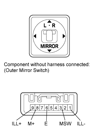
INSPECT OUTER MIRROR SWITCH ASSEMBLY
-
Inspect the mirror control switch.
-
Select "L" on the left/right adjustment switch.
-
Measure the resistance according to the value(s) in the table below.
Standard Resistance Tester Connection Switch Condition Specified Condition 8 (M+) - 6 (E) Up switch pushed 90 to 110 Ω Down switch pushed 437 to 502 Ω Left switch pushed 744 to 856 Ω Right switch pushed 207 to 253 Ω No switches pushed 10 kΩ or higher 3 (MSW) - 6 (E) Adjustment switch in L position 90 to 110 Ω Adjustment switch in neutral position 10 kΩ or higher If the result is not as specified, replace the outer mirror switch assembly.
-
Select "R" on the left/right adjustment switch.
-
Measure the resistance according to the value(s) in the table below.
Standard Resistance Tester Connection Switch Condition Specified Condition 8 (M+) - 6 (E) Up switch pushed 90 to 110 Ω Down switch pushed 437 to 502 Ω Left switch pushed 744 to 856 Ω Right switch pushed 207 to 253 Ω No switches pushed 10 kΩ or higher 3 (MSW) - 6 (E) Adjustment switch in R position Below 1 Ω Adjustment switch in neutral position 10 kΩ or higher If the result is not as specified, replace the outer mirror switch assembly.
-
Inspect the switch illumination.
Apply battery voltage between the terminals of the light, and check the operation of the light.
OK Measurement Condition Specified Condition Battery positive (+) → Terminal 9 (ILL+)
Battery negative (-) → Terminal 1 (ILL-)
Light comes on If the result is not as specified, replace the outer mirror switch assembly.
-
-
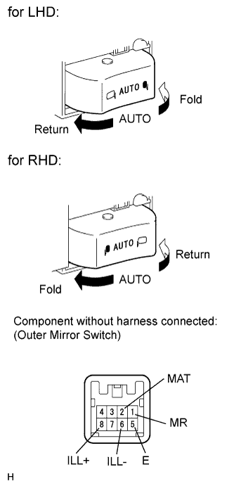
Inspect the mirror retract switch.
-
Measure the resistance according to the value(s) in the table below.
Standard Resistance Tester Connection Switch Condition Specified Condition 5 (E) - 1 (MR) Mirror retract switch in fold position Below 1 Ω Mirror retract switch not in fold position 10 kΩ or higher 5 (E) - 2 (MAT) Mirror retract switch in AUTO position Below 1 Ω Mirror retract switch not in AUTO position 10 kΩ or higher If the result is not as specified, replace the outer mirror switch assembly.
-
Inspect the switch illumination.
Apply battery voltage between the terminals of the light, and check the operation of the light.
OK Measurement Condition Specified Condition Battery positive (+) → Terminal 8 (ILL+)
Battery negative (-) → Terminal 6 (ILL-)
Light comes on If the result is not as specified, replace the outer mirror switch assembly.
-
-