TAIL GATE INSPECTION

-
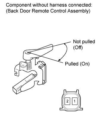
INSPECT BACK DOOR REMOTE CONTROL ASSEMBLY
-
Measure the resistance according to the value(s) in the table below.
Standard Resistance Tester Connection Switch Condition Specified Condition 1 - 2 Back door remote control is pulled (on) Below 1 Ω 1 - 2 Back door remote control is not pulled (off) 10 kΩ or higher If the result is not as specified, replace the back door remote control assembly.
-
-
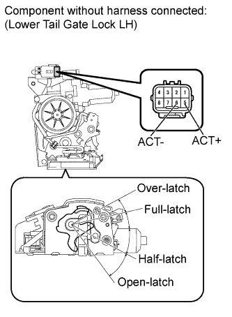
INSPECT LOWER TAIL GATE LOCK ASSEMBLY LH
-
Operation check:
-
Set the lower tail gate lock LH to the full-latch position.
-
Apply battery voltage and check operation of the lower tail gate lock motor LH.
OK Measurement Condition Specified Condition Battery positive (+) → Terminal 6 (ACT-)
Battery negative (-) → Terminal 5 (ACT+)
Latch turns to open-latch position If the result is not as specified, replace the lower tail gate lock assembly LH.
-
Set the lower tail gate lock LH to the half-latch position.
-
Apply battery voltage and check operation of the lower tail gate lock motor LH.
OK Measurement Condition Specified Condition Battery positive (+) → Terminal 5 (ACT+)
Battery negative (-) → Terminal 6 (ACT-)
Latch turns to over-latch position If the result is not as specified, replace the lower tail gate lock assembly LH.
-
-
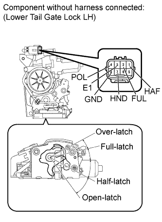
Resistance check:
-
Measure the resistance according of the value(s) in the table below.
Standard Resistance Close Position Switch Tester Connection Condition Specified Condition 7 (HND) - 8 (GND) Over-latch Below 1 Ω 7 (HND) - 8 (GND) Full-latch 10 kΩ or higher 7 (HND) - 8 (GND) Half-latch 10 kΩ or higher 7 (HND) - 8 (GND) Open-latch 10 kΩ or higher If the result is not as specified, replace the lower tail gate lock assembly LH.
Lower Tail Gate Courtesy Switch Tester Connection Condition Specified Condition 2 (FUL) - 3 (E1) Over-latch 10 kΩ or higher 2 (FUL) - 3 (E1) Full-latch 10 kΩ or higher 2 (FUL) - 3 (E1) Half-latch Below 1 Ω 2 (FUL) - 3 (E1) Open-latch Below 1 Ω If the result is not as specified, replace the lower tail gate lock assembly LH.
Half-latch Switch Tester Connection Condition Specified Condition 1 (HAF) - 3 (E1) Over-latch 10 kΩ or higher 1 (HAF) - 3 (E1) Full-latch Below 1 Ω 1 (HAF) - 3 (E1) Half-latch 10 kΩ or higher 1 (HAF) - 3 (E1) Open-latch Below 1 Ω If the result is not as specified, replace the lower tail gate lock assembly LH.
Pawl Switch Tester Connection Condition Specified Condition 4 (POL) - 3 (E1) Over-latch 10 kΩ or higher 4 (POL) - 3 (E1) Full-latch Below 1 Ω 4 (POL) - 3 (E1) Half-latch Below 1 Ω 4 (POL) - 3 (E1) Open-latch 10 kΩ or higher If the result is not as specified, replace the lower tail gate lock assembly LH.
-
-
-
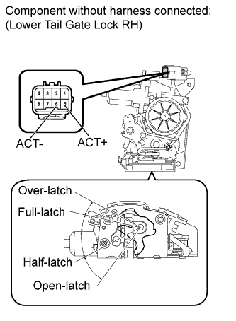
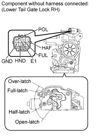
INSPECT LOWER TAIL GATE LOCK ASSEMBLY RH
-
Operation check:
-
Set the lower tail gate lock RH to the full-latch position.
-
Apply battery voltage and check operation of the lower tail gate lock motor RH.
OK Measurement Condition Specified Condition Battery positive (+) → Terminal 6 (ACT-)
Battery negative (-) → Terminal 5 (ACT+)
Latch turns to open-latch position If the result is not as specified, replace the lower tail gate lock assembly RH.
-
Set the lower tail gate lock RH to the half-latch position.
-
Apply battery voltage and check operation of the lower tail gate lock motor RH.
OK Measurement Condition Specified Condition Battery positive (+) → Terminal 5 (ACT+)
Battery negative (-) → Terminal 6 (ACT-)
Latch turns to over-latch position If the result is not as specified, replace the lower tail gate lock assembly RH.
-
-
Resistance check:
-
Measure the resistance according of the value(s) in the table below.
Standard Resistance Close Position Switch Tester Connection Condition Specified Condition 7 (HND) - 8 (GND) Over-latch Below 1 Ω 7 (HND) - 8 (GND) Full-latch 10 kΩ or higher 7 (HND) - 8 (GND) Half-latch 10 kΩ or higher 7 (HND) - 8 (GND) Open-latch 10 kΩ or higher If the result is not as specified, replace the lower tail gate lock assembly RH.
Lower Tail Gate Courtesy Switch Tester Connection Condition Specified Condition 2 (FUL) - 3 (E1) Over-latch 10 kΩ or higher 2 (FUL) - 3 (E1) Full-latch 10 kΩ or higher 2 (FUL) - 3 (E1) Half-latch Below 1 Ω 2 (FUL) - 3 (E1) Open-latch Below 1 Ω If the result is not as specified, replace the lower tail gate lock assembly RH.
Half-latch Switch Tester Connection Condition Specified Condition 1 (HAF) - 3 (E1) Over-latch 10 kΩ or higher 1 (HAF) - 3 (E1) Full-latch Below 1 Ω 1 (HAF) - 3 (E1) Half-latch 10 kΩ or higher 1 (HAF) - 3 (E1) Open-latch Below 1 Ω If the result is not as specified, replace the lower tail gate lock assembly RH.
Pawl Switch Tester Connection Condition Specified Condition 4 (POL) - 3 (E1) Over-latch 10 kΩ or higher 4 (POL) - 3 (E1) Full-latch Below 1 Ω 4 (POL) - 3 (E1) Half-latch Below 1 Ω 4 (POL) - 3 (E1) Open-latch 10 kΩ or higher If the result is not as specified, replace the lower tail gate lock assembly RH.
-
-