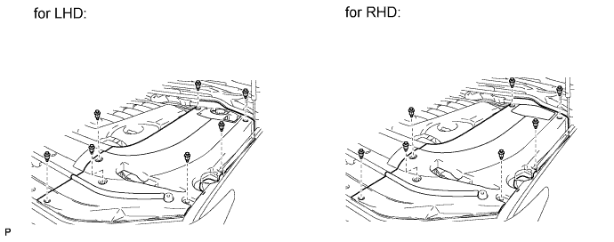
FUEL LID LOCK CONTROL CABLE ASSEMBLY (for RHD) REMOVAL

-
REMOVE ENGINE ROOM SIDE COVER LH
-
Remove the 7 clips and engine room side cover LH.
-
-
REMOVE REAR SEAT CUSHION HINGE COVER RH (w/ Rear No. 2 Seat)
-
Apply protective tape to the rear seatback lock striker as shown in the illustration to prevent the seat from locking.
-
Operate the power seat switch and move the seat to the storage position.
Tech Tips
Make sure that the lock and striker are not engaged.
-
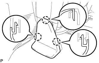
Using a screwdriver, detach the 3 claws and remove the cover.
Tech Tips
Tape the screwdriver tip before use.
-
-
REMOVE REAR NO. 2 SEAT HINGE COVER RH (w/ Rear No. 2 Seat)
-
Detach the 3 claws and 2 clips, and then remove the cover.
-
-
DISCONNECT CABLE FROM NEGATIVE BATTERY TERMINAL
CAUTION:
Wait at least 90 seconds after disconnecting the cable from the negative (-) battery terminal to disable the SRS system.
Note
-
w/ Navigation System:
After the engine switch is turned off, the HDD navigation system requires approximately 6 minutes to record various types of memory and settings. As a result, after turning the engine switch off, wait 6 minutes or more before disconnecting the cable from the negative (-) battery terminal.
-
When disconnecting the cable, some systems need to be initialized after the cable is reconnected Click here.
-
-
REMOVE REAR NO. 2 SEAT ASSEMBLY (w/ Rear No. 2 Seat)
-
Disconnect the connector.
-
Remove the 4 bolts and seat assembly.
Note
Be careful not to damage the vehicle body.
-
-
REMOVE INSTRUMENT SIDE PANEL RH
-
w/o Airbag Cut Off Switch:
-
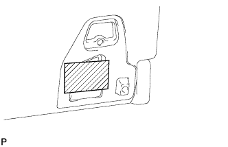
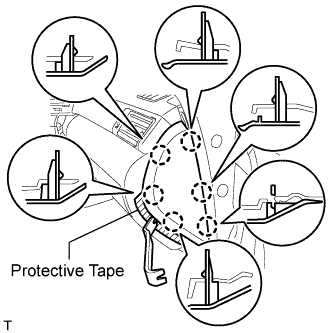
Place protective tape as shown in the illustration.
-
Using a moulding remover, detach the 6 claws and remove the side panel.
-
-
w/ Airbag Cut Off Switch:
-
Place protective tape as shown in the illustration.
-
Using a moulding remover, detach the 6 claws.
-
Remove the side panel and disconnect the connector.
-
-
-
REMOVE COWL SIDE TRIM BOARD RH
-
Remove the cap nut.
-
Detach the 2 clips and remove the trim board.
-
-
REMOVE FRONT DOOR SCUFF PLATE RH
Tech Tips
Use the same procedures described for the LH side.
-
REMOVE REAR STEP COVER
Tech Tips
Use the same procedure to remove the step cover on the other side.
-
w/o Illumination Type Front Door Scuff Plate:
Detach the 2 claws and remove the step cover.
-
w/ Illumination Type Front Door Scuff Plate:
Detach the 4 claws and remove the step cover.
-
-
REMOVE REAR DOOR SCUFF PLATE RH
Tech Tips
Use the same procedures described for the LH side.
-
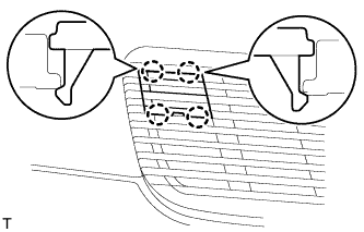
REMOVE REAR FLOOR MAT REAR SUPPORT PLATE
-
Detach the 6 clips and 4 claws, and remove the support plate.
-
-
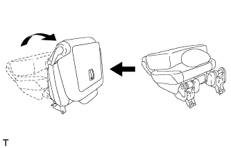
REMOVE FRONT QUARTER TRIM PANEL ASSEMBLY RH
Tech Tips
When removing the front quarter trim panel, operate the reclining adjuster release handle and move the No. 1 rear seat to the position shown in the illustration.
-
Detach the 3 claws and remove the cover.
-
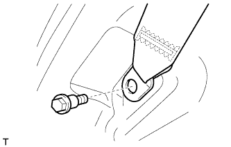
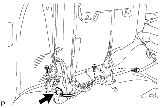
Remove the bolt and rear No. 1 seat belt anchor.
-
Detach the 3 claws and remove the cover.
-
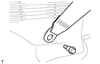
Remove the bolt and rear No. 2 seat belt anchor.
-
Remove the clip.
-
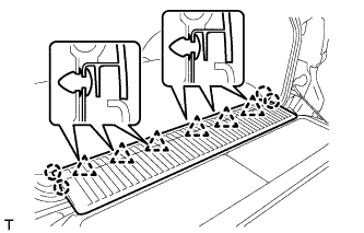
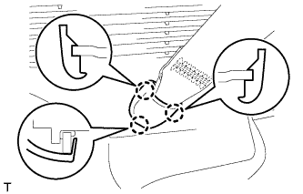
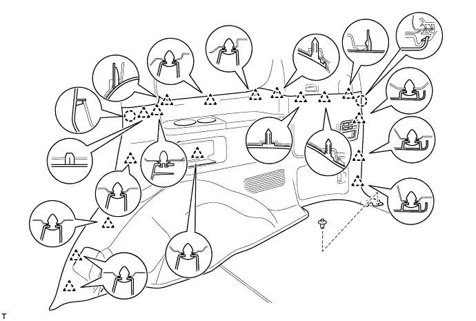
Detach the 17 clips and 2 claws.
-
Disconnect the thermistor connector and then remove the quarter trim panel.
-
-
REMOVE NO. 1 WOOFER BOX SPEAKER ASSEMBLY (for 19 Speakers)
-
Disconnect the connector.
-
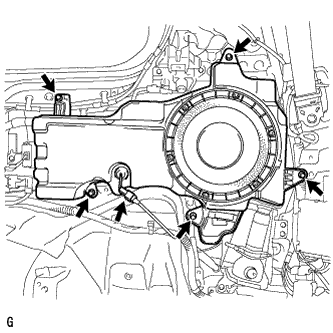
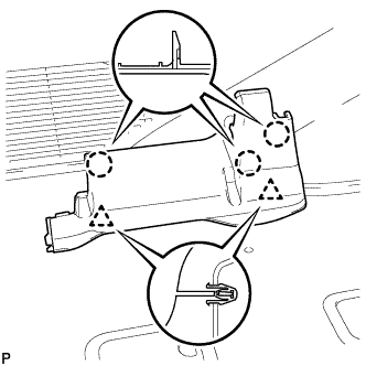
Remove the 5 bolts and box speaker.
-
-
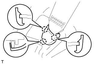
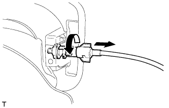
REMOVE FUEL FILLER OPENING LID LOCK RETAINER
-
Turn the cable counterclockwise and remove the cable from the retainer.
-
Turn the lock retainer counterclockwise and remove the lock retainer.
-
-
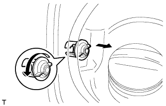
REMOVE FUEL LID LOCK OPEN LEVER SUB-ASSEMBLY
-

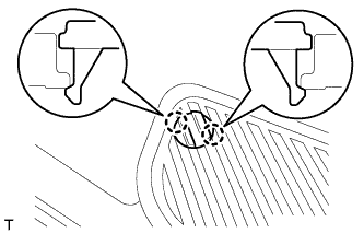
Detach the 2 claws.
-
Disconnect the fuel lid lock control cable and remove the fuel lid lock open lever.
-
-
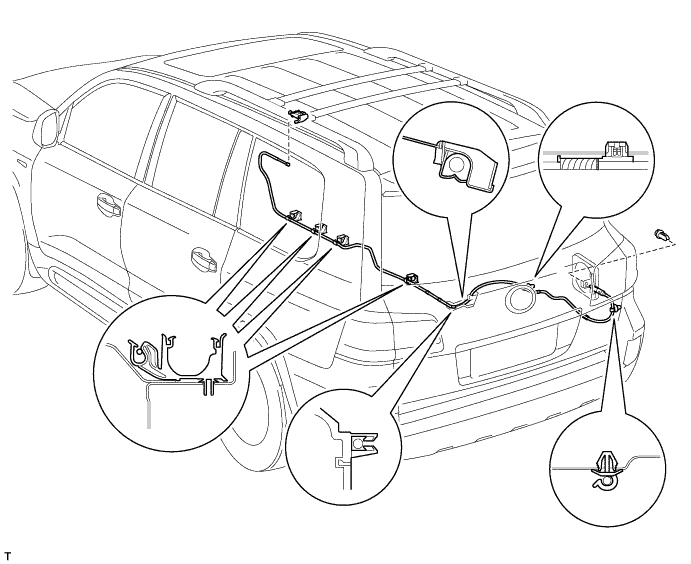
REMOVE FUEL LID LOCK CONTROL CABLE SUB-ASSEMBLY
-
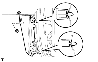
Using a screwdriver, disconnect the clamps shown in the illustration.
Tech Tips
Tape the screwdriver tip before use.
-
Remove the lock control cable.
-