POWER BACK DOOR DRIVE UNIT INSTALLATION

-
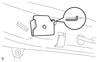
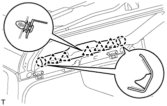
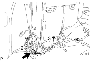
INSTALL POWER BACK DOOR UNIT ASSEMBLY
-
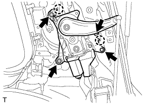
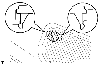
Attach the 2 claws to install the power back door unit.
-
Install the 4 bolts.
- Torque:
- 14 N*m { 143 kgf*cm, 10 ft.*lbf }
-
Connect the connector.
-
-
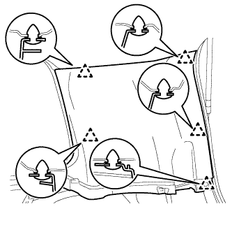
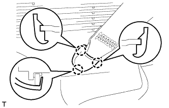
INSTALL REAR UPPER PILLAR GARNISH RH
-
w/o Power Back Door:
-
Attach the 5 clips to install the rear upper pillar garnish.
-
-
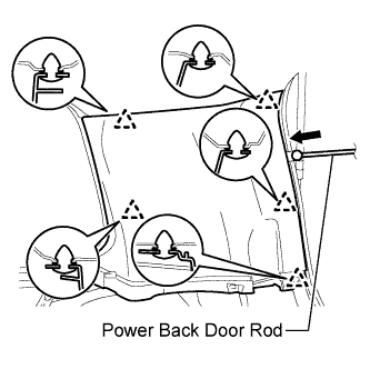
w/ Power Back Door:
-
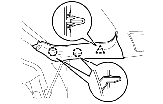
Pass the power back door rod through the rear upper pillar garnish.
-
Attach the 5 clips to install the rear upper pillar garnish.
-
-
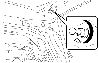
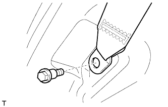
Install the seat belt shoulder anchor with the bolt.
- Torque:
- 42 N*m { 428 kgf*cm, 31 ft.*lbf }
-

Attach the 2 claws to close the seat belt shoulder anchor cover.
-
-
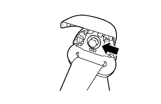
INSTALL BACK DOOR SERVICE HOLE COVER RH
-
When reusing the power back door rod:
-
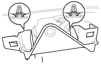
Install the back door stay plate.
-
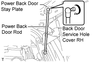
Pass the power back door rod through the hole of the back door service hole cover and install the rod with the bolt.
- Torque:
- 18 N*m { 184 kgf*cm, 13 ft.*lbf }
-
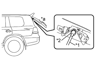
Text in Illustration *1 Power Back Door Rod *2 Hole of Back Door Service Hole Cover *a Back Door is Half-open Move the back door to a half-open position so that the hole in the center of the back door service hole cover is aligned lengthwise with the power back door rod.
-
Attach the 2 clips and install the back door service hole cover.
Note
If the back door is in a fully-open position, the power back door rod will interfere with the hole of the back door service hole cover, so do not perform this operation with the back door in a fully open position.
-
-
When installing a new power back door rod:
-
Install the back door stay plate.
-
Install the back door stay bolt.
- Torque:
- 18 N*m { 184 kgf*cm, 13 ft.*lbf }
-
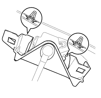
Attach the 2 clips to install the service hole cover.
-
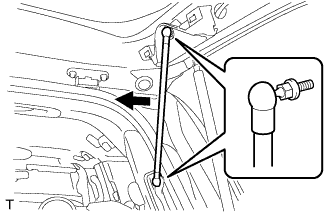
Attach the ball joints to install the power back door rod.
-
-
-
INSTALL BACK DOOR SIDE GARNISH RH
-
w/o Power Back Door:
Tech Tips
Use the same procedures described for the LH side.
-
w/ Power Back Door:
-
Attach the clip and 2 claws to install the back door side garnish.
-
-
-
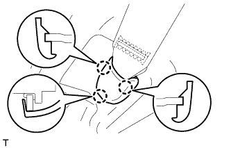
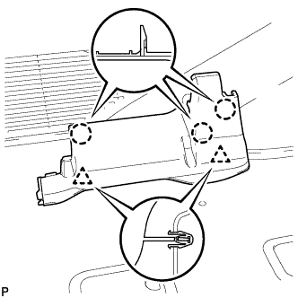
INSTALL CENTER BACK DOOR GARNISH
-
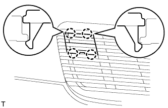
Attach the 5 clips and 2 claws to install the back door garnish.
-
-
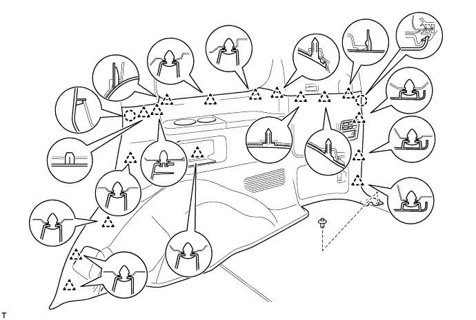
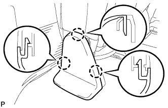
INSTALL FRONT QUARTER TRIM PANEL ASSEMBLY RH
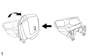
Tech Tips
When installing the front quarter trim panel, operate the reclining adjuster release handle and move the No. 1 rear seat to the position shown in the illustration.
-
Connect the thermistor connector.
-
Attach the 17 clips and 2 claws to install the quarter trim panel.
-
Install the clip.
-
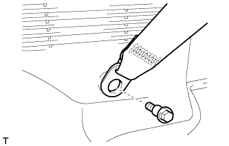
Install the rear No. 2 seat belt anchor with the bolt.
- Torque:
- 42 N*m { 428 kgf*cm, 31 ft.*lbf }
-
Attach the 3 claws to install the cover.
-
Install the rear No. 1 seat belt anchor with the bolt.
- Torque:
- 42 N*m { 428 kgf*cm, 31 ft.*lbf }
-
Attach the 3 claws to install the cover.
-
-
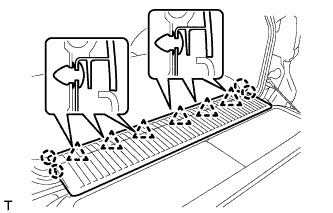
INSTALL REAR FLOOR MAT REAR SUPPORT PLATE
-
Attach the 6 clips and 4 claws to install the support plate.
-
-
INSTALL REAR DOOR SCUFF PLATE RH
Tech Tips
Use the same procedures described for the LH side.
-
INSTALL REAR STEP COVER
Tech Tips
Use the same procedure to install the step cover on the other side.
-
w/o Illumination Type Front Door Scuff Plate:
Attach the 2 claws to install the step cover.
-
w/ Illumination Type Front Door Scuff Plate:
Attach the 4 claws to install the step cover.
-
-
INSTALL REAR NO. 2 SEAT ASSEMBLY (w/ Rear No. 2 Seat)
-
Temporarily install the seat with the 4 bolts.
Note
Be careful not to damage the vehicle body.
-
Tighten the bolts in the order shown in the illustration.
- Torque:
- 37 N*m { 377 kgf*cm, 27 ft.*lbf }
-
Connect the connector.
-
-
CONNECT CABLE TO NEGATIVE BATTERY TERMINAL
Note
When disconnecting the cable, some systems need to be initialized after the cable is reconnected Click here.
-
INSTALL REAR NO. 2 SEAT HINGE COVER RH (w/ Rear No. 2 Seat)
-
Attach the 3 claws and 2 clips to install the cover.
-
-
INSTALL REAR SEAT CUSHION HINGE COVER RH (w/ Rear No. 2 Seat)
-
Attach the 3 claws to install the cover.
-
Return the seat to the upright position.
-
-
INSTALL ENGINE ROOM SIDE COVER LH
-
Install the engine room side cover LH with the 7 clips.
-