POWER MIRROR CONTROL SYSTEM Power Mirrors do not Return to Memorized Position
SYSTEM DESCRIPTION
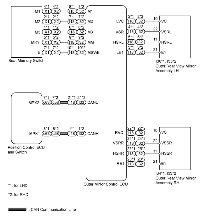
When the seat memory switch 1, seat memory switch 2 or seat memory switch 3 is pressed, the position control ECU and switch mirror position signal is sent through the CAN communication line to the outer mirror control ECU. The outer mirror control ECU then activates the mirror control motors to move the mirrors to the previously recorded positions.
WIRING DIAGRAM
INSPECTION PROCEDURE
PROCEDURE
-
CHECK DTC
-
Use the intelligent tester to check if the CAN communication system is functioning normally.
Result Result Proceed to CAN DTC is not output A CAN DTC is output (for LHD) B CAN DTC is output (for RHD) C
B 
GO TO CAN COMMUNICATION SYSTEM Click here
C
GO TO CAN COMMUNICATION SYSTEM Click here
A 
-
-
CHECK POWER MIRROR CONTROL FUNCTION
-
Check that the mirror surface positions of the outer rear view mirror LH and RH can be moved using the outer mirror switch.
OK Mirror surface positions of the outer rear view mirror LH and RH can be moved using the outer mirror switch.
NG
PROCEED TO NEXT INSPECTION PROCEDURE SHOWN IN PROBLEM SYMPTOMS TABLE Click here
OK
-
-
READ VALUE USING INTELLIGENT TESTER (MIRROR POSITION MEMORY)
-
Check the Data List for proper functioning of the mirror position memory Click here.
Mirror Tester Display Measurement Item/Display Normal Condition Diagnostic Note Mirror Memory No.1 Mirror position memorized in seat memory switch 1 / ON or OFF ON: Memorized
OFF: Not memorized
- Mirror Memory No.2 Mirror position memorized in seat memory switch 2 / ON or OFF ON: Memorized
OFF: Not memorized
- Mirror Memory No.3 Mirror position memorized in seat memory switch 3 / ON or OFF ON: Memorized
OFF: Not memorized
- OK On tester screen, each item changes between ON and OFF according to above chart.
NG
REPLACE OUTER MIRROR CONTROL ECU Click here
OK
-
-
READ VALUE USING INTELLIGENT TESTER (MIRROR POSITION SENSOR)
-
Check the Data List for proper functioning of the mirror position sensor Click here.
Mirror Tester Display Measurement Item/Display Normal Condition Diagnostic Note RH Mir Position Sensor V RH side mirror vertical sensor voltage / MIN: 0 V, MAX: 5 V Within range from 0 to 5 V - RH Mir Position Sensor H RH side mirror horizontal sensor voltage / MIN: 0 V, MAX: 5 V Within range from 0 to 5 V - LH Mir Position Sensor V LH side mirror vertical sensor voltage / MIN: 0 V, MAX: 5 V Within range from 0 to 5 V - LH Mir Position Sensor H LH side mirror horizontal sensor voltage / MIN: 0 V, MAX: 5 V Within range from 0 to 5 V - OK When mirror control switch is operated, voltage changes within range shown in above chart. Result Result Proceed to LH side mirror does not operate normally A RH side mirror does not operate normally B Mirror operates normally C
B 
CHECK OUTER MIRROR CONTROL ECU (POWER SOURCE FOR MIRROR POSITION SENSOR) Click here
C
GO TO FRONT POWER SEAT CONTROL SYSTEM Click here
A
-
-
CHECK OUTER MIRROR CONTROL ECU (POWER SOURCE FOR MIRROR POSITION SENSOR)
-
for LHD:
-
Measure the voltage according to the value(s) in the table below.
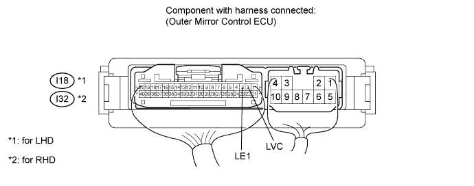
Standard Voltage Tester Connection Switch Condition Specified Condition I18-2 (LVC) - I18-3 (LE1) Engine switch on (IG) 4.7 to 5.5 V -
Measure the resistance according to the value(s) in the table below.
Standard Resistance Tester Connection Condition Specified Condition I18-3 (LE1) - Body ground Always Below 1 Ω
-
-
for RHD:
-
Measure the voltage according to the value(s) in the table below.
Standard Voltage Tester Connection Switch Condition Specified Condition I32-2 (LVC) - I32-3 (LE1) Engine switch on (IG) 4.7 to 5.5 V -
Measure the resistance according to the value(s) in the table below.
Standard Resistance Tester Connection Condition Specified Condition I32-3 (LE1) - Body ground Always Below 1 Ω
-
NG
REPLACE OUTER MIRROR CONTROL ECU Click here
OK
-
-
CHECK HARNESS AND CONNECTOR (OUTER REAR VIEW MIRROR LH - OUTER MIRROR CONTROL ECU)
-
for LHD:
-
Disconnect the I18 ECU connector.
-
Disconnect the I36 mirror connector.
-
Measure the resistance according to the value(s) in the table below.
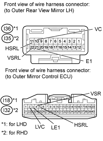
Standard Resistance Tester Connection Condition Specified Condition I18-2 (LVC) - I36-10 (VC) Always Below 1 Ω I18-3 (LE1) - I36-21 (E1) I18-4 (VSR) - I36-22 (VSRL) I18-5 (HSRL) - I36-11 (HSRL) I36-10 (VC) - Body ground Always 10 kΩ or higher I36-21 (E1) - Body ground I36-22 (VSRL) - Body ground I36-11 (HSRL) - Body ground
-
-
for RHD:
-
Disconnect the I32 ECU connector.
-
Disconnect the I35 mirror connector.
-
Measure the resistance according to the value(s) in the table below.
Standard Resistance Tester Connection Condition Specified Condition I32-2 (LVC) - I35-10 (VC) Always Below 1 Ω I32-3 (LE1) - I35-21 (E1) I32-4 (VSR) - I35-22 (VSRL) I32-5 (HSRL) - I35-11 (HSRL) I35-10 (VC) - Body ground Always 10 kΩ or higher I35-21 (E1) - Body ground I35-22 (VSRL) - Body ground I35-11 (HSRL) - Body ground
-
NG
REPAIR OR REPLACE HARNESS OR CONNECTOR
OK 
REPLACE OUTER REAR VIEW MIRROR ASSEMBLY LH Click here
-
-
CHECK OUTER MIRROR CONTROL ECU (POWER SOURCE FOR MIRROR POSITION SENSOR)
-
for LHD:
-
Measure the voltage according to the value(s) in the table below.
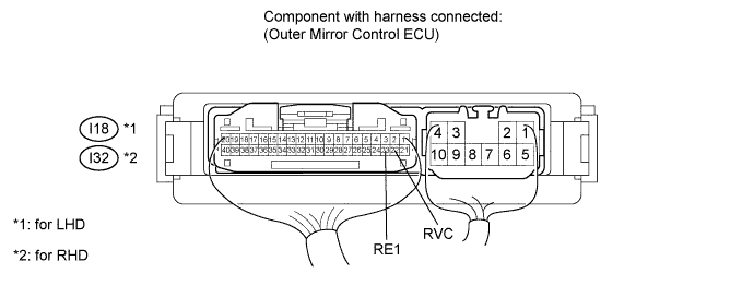
Standard Voltage Tester Connection Switch Condition Specified Condition I18-22 (RVC) - I18-23 (RE1) Engine switch on (IG) 4.7 to 5.5 V -
Measure the resistance according to the value(s) in the table below.
Standard Resistance Tester Connection Condition Specified Condition I18-23 (RE1) - Body ground Always Below 1 Ω
-
-
for RHD:
-
Measure the voltage according to the value(s) in the table below.
Standard Voltage Tester Connection Switch Condition Specified Condition I32-22 (RVC) - I32-23 (RE1) Engine switch on (IG) 4.7 to 5.5 V -
Measure the resistance according to the value(s) in the table below.
Standard Resistance Tester Connection Condition Specified Condition I32-23 (RE1) - Body ground Always Below 1 Ω
-
NG
REPLACE OUTER MIRROR CONTROL ECU Click here
OK
-
-
CHECK HARNESS AND CONNECTOR (OUTER REAR VIEW MIRROR RH - OUTER MIRROR CONTROL ECU)
-
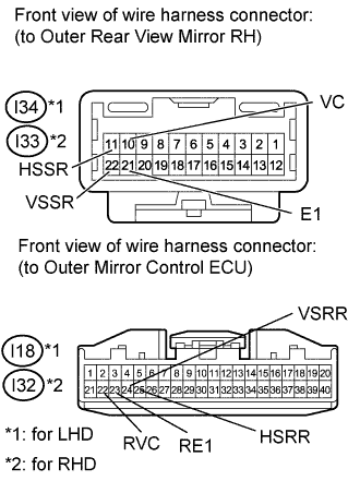
for LHD:
-
Disconnect the I18 ECU connector.
-
Disconnect the I34 mirror connector.
-
Measure the resistance according to the value(s) in the table below.
Standard Resistance Tester Connection Condition Specified Condition I18-22 (RVC) - I34-10 (VC) Always Below 1 Ω I18-23 (RE1) - I34-21 (E1) I18-24 (VSRR) - I34-22 (VSSR) I18-25 (HSRR) - I34-11 (HSSR) I34-10 (VC) - Body ground Always 10 kΩ or higher I34-21 (E1) - Body ground I34-22 (VSSR) - Body ground I34-11 (HSSR) - Body ground
-
-
for RHD:
-
Disconnect the I32 ECU connector.
-
Disconnect the I33 mirror connector.
-
Measure the resistance according to the value(s) in the table below.
Standard Resistance Tester Connection Condition Specified Condition I32-22 (RVC) - I33-10 (VC) Always Below 1 Ω I32-23 (RE1) - I33-21 (E1) I32-24 (VSRR) - I33-22 (VSSR) I32-25 (HSRR) - I33-11 (HSSR) I33-10 (VC) - Body ground Always 10 kΩ or higher I33-21 (E1) - Body ground I33-22 (VSSR) - Body ground I33-11 (HSSR) - Body ground
-
NG
REPAIR OR REPLACE HARNESS OR CONNECTOR
OK
REPLACE OUTER REAR VIEW MIRROR ASSEMBLY RH Click here
-