POWER BACK DOOR CONTROL SWITCH REMOVAL

Tech Tips
-
Use the same procedures for LHD and RHD vehicles.
-
The procedures listed below are for LHD vehicles.
-
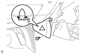
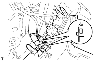
REMOVE INSTRUMENT SIDE PANEL LH
-
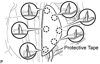
Place protective tape as shown in the illustration.
-
Using a moulding remover, detach the 6 claws and remove the side panel.
-
-
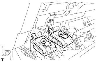
REMOVE NO. 1 SWITCH HOLE BASE
-
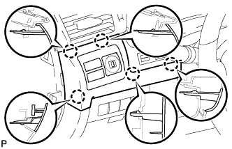
Detach the 5 claws.
-
Disconnect the connectors and remove the switch hole base.
-
-
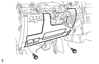
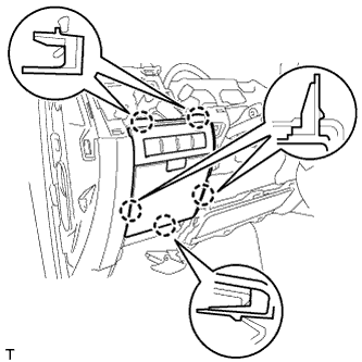
REMOVE NO. 1 INSTRUMENT PANEL UNDER COVER SUB-ASSEMBLY
-
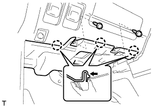
Remove the 2 screws.
-
Detach the 3 claws.
-
Remove the under cover and disconnect the connectors.
-
-
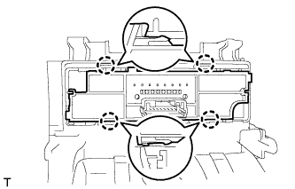
REMOVE LOWER INSTRUMENT PANEL PAD SUB-ASSEMBLY LH
-
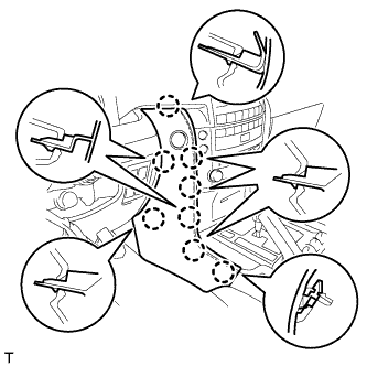
Detach the 8 claws.
-
Disconnect the connector and remove the panel pad.
-
-
REMOVE INNER NO. 1 INSTRUMENT PANEL BRACKET COVER LH
-
Remove the clip.
-
Detach the clip and remove the cover.
-
-
REMOVE LOWER NO. 1 INSTRUMENT PANEL FINISH PANEL
-
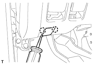
Using a screwdriver, detach the 2 claws and open the hole cover.
Tech Tips
Tape the screwdriver tip before use.
-
Remove the 2 bolts.
-
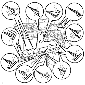
Detach the 16 claws.
-
Detach the 2 claws and remove the sensor.
-
Detach the 2 claws and disconnect the 2 control cables.
-
Remove the finish panel and then disconnect the connectors.
-
-
REMOVE INSTRUMENT PANEL BOX ASSEMBLY
-
Detach the 5 claws.
-
Remove the box and then disconnect the connectors.
-
-
REMOVE COMBINATION SWITCH ASSEMBLY
-
Detach the 4 claws and remove the switch.
-