BACK DOOR REASSEMBLY

-
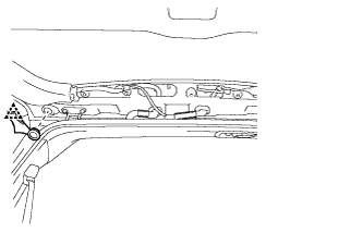
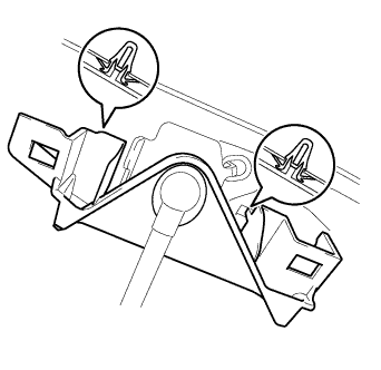
INSTALL BACK DOOR STAY ASSEMBLY LH
-
When reusing the back door stay:
-
Clean the threaded surface on the vehicle body with a non-residue solvent.
-
Apply adhesive to the threads of the 2 bolts.
Adhesive Toyota Genuine Adhesive 1324, Three Bond 1324 or equivalent -
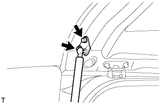
Install the back door stay with the 2 bolts.
- Torque:
- 22 N*m { 224 kgf*cm, 16 ft.*lbf }
CAUTION:
Install the door stay while supporting the back door with one hand.
-
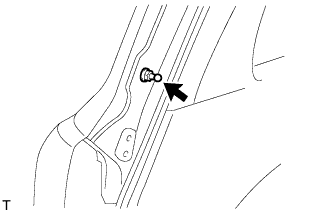
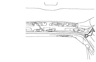
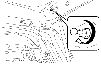
Apply adhesive to the threads of the bolt.
Adhesive Toyota Genuine Adhesive 1324, Three Bond 1324 or equivalent -
Install the back door stay bolt to the body.
- Torque:
- 18 N*m { 184 kgf*cm, 13 ft.*lbf }
CAUTION:
Install the door stay bolt while supporting the back door with one hand.
-
-
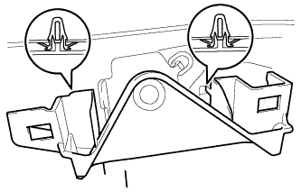
When replacing the back door stay with a new one:
-
Clean the threaded surface on the vehicle body with a non-residue solvent.
-
Apply adhesive to the threads of the bolt.
Adhesive Toyota Genuine Adhesive 1324, Three Bond 1324 or equivalent -
Install the back door stay bolt to the body.
- Torque:
- 18 N*m { 184 kgf*cm, 13 ft.*lbf }
CAUTION:
Install the door stay bolt while supporting the back door with one hand.
-
Apply adhesive to the threads of the 2 bolts.
Adhesive Toyota Genuine Adhesive 1324, Three Bond 1324 or equivalent -
Install the back door stay with the 2 bolts.
- Torque:
- 22 N*m { 224 kgf*cm, 16 ft.*lbf }
CAUTION:
Install the door stay while supporting the back door with one hand.
-
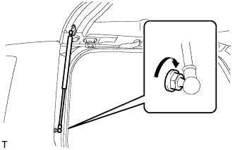
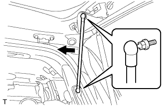
Connect the ball joint of the back door stay bolt to the back door stay assembly LH.
-
Check that the back door stay assembly is securely installed.
-
-
-
INSTALL BACK DOOR STAY ASSEMBLY RH
Tech Tips
Use the same procedures described for the LH side.
-
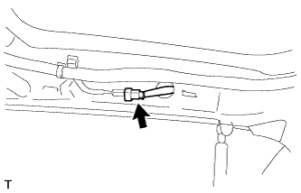
INSTALL REAR WASHER NOZZLE
-
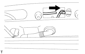
Connect the hose.
-
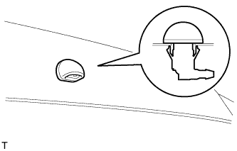
Attach the 2 claws to install the washer nozzle.
-
-
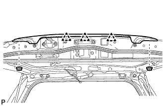
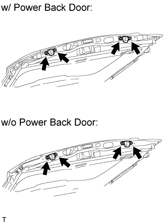
INSTALL REAR SPOILER SUB-ASSEMBLY
-
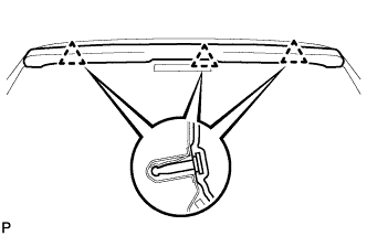
Attach the 3 clips to install the rear spoiler.
-
w/ Power Back Door:
Install the 4 bolts and 2 hole plugs.
-
w/o Power Back Door:
Install the 4 bolts.
-
-
INSTALL BACK DOOR GLASS CHANNEL LH (w/o Power Back Door)
-
Attach the clip and install the back door glass channel.
-
-
INSTALL BACK DOOR GLASS CHANNEL RH (w/o Power Back Door)
-
Attach the clip and install the back door glass channel.
-
-
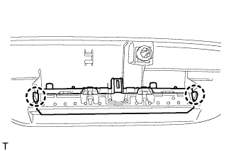
INSTALL BACK DOOR GARNISH SUB-ASSEMBLY OUTSIDE
-
Attach the 3 clips to install the garnish.
-
Install the 2 nuts.
-
-
INSTALL LOWER BACK DOOR STOPPER
-
Install the lower back door stopper with the bolt.
-
-
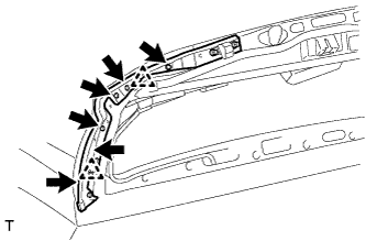
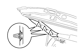
INSTALL LIFT GATE WEATHERSTRIP
-
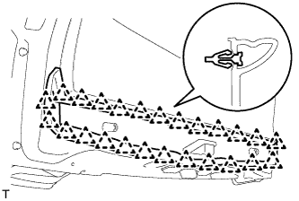
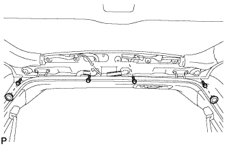
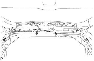
Attach the 25 clips to install the lift gate weatherstrip.
Note
Do not pull strongly on the weatherstrip as it may be damaged.
-
-
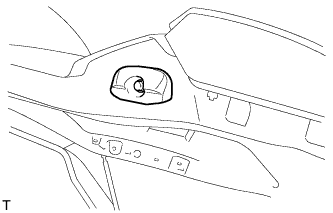
INSTALL REAR TELEVISION CAMERA ASSEMBLY
-
Connect the connector.
-
Attach the 2 screws grommet to install the rear television camera assembly.
-
Using a T30 "TORX" socket wrench, install the rear television camera with the 2 screws.
-
-
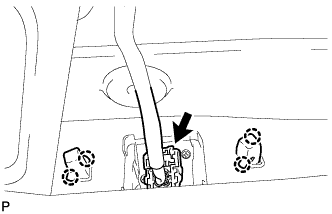
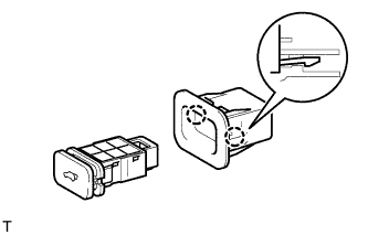
INSTALL BACK DOOR OPENER SWITCH ASSEMBLY
-
Connect the connector and then install the back door opener switch.
-
Install the 2 screws.
- Torque:
- 7.5 N*m { 76 kgf*cm, 66 in.*lbf }
-
-
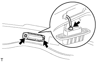
INSTALL LICENSE PLATE LIGHT ASSEMBLY
-
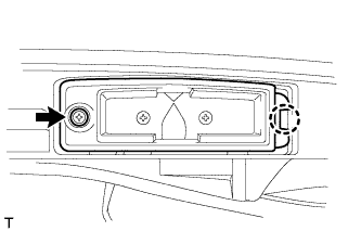
Attach the 2 claws to install the 2 lights.
-
Install the 2 screws.
-
-
INSTALL BACK DOOR GARNISH RETAINER SUB-ASSEMBLY
-
Connect the connector.
-
Using a T30 "TORX" socket wrench, attach the 2 clips and install the garnish with the 2 screws.
-
-
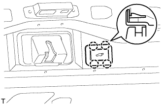
INSTALL BACK DOOR CONTROL SWITCH (w/ Power Back Door)
-
Attach the 2 claws to install the door control switch.
-
-
INSTALL SWITCH BEZEL (w/ Power Back Door)
-
Attach the 4 claws to install the switch bezel.
-
Connect the connector.
-
-
INSTALL BACK DOOR LOCK PROTECTOR (w/ Power Back Door)
-
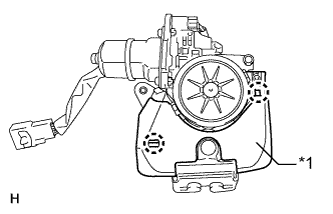
Text in Illustration *1 Protector (A) Attach the 2 claws to install the protector (A).
-
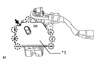
Text in Illustration *1 Protector (B) Attach the 7 claws to install the protector (B).
-
Install the screw.
-
-
INSTALL BACK DOOR LOCK ASSEMBLY
-
w/o Power Back Door:
-
Install the back door lock with the 3 bolts.
- Torque:
- 13 N*m { 133 kgf*cm, 10 ft.*lbf }
-
Connect the connector.
-
-
w/ Power Back Door:
-
Install the back door lock with the 4 bolts.
- Torque:
- 13 N*m { 133 kgf*cm, 10 ft.*lbf }
-
Connect the connector.
-
-
-
INSTALL BACK DOOR LOCK COVER
-
Attach the 4 claws to install the back door lock cover.
-
-
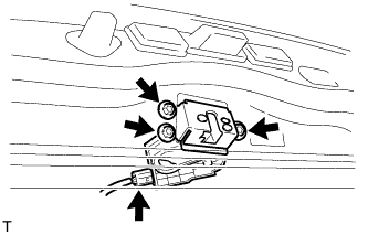
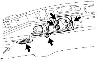
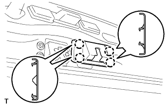
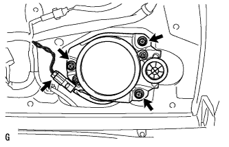
INSTALL REAR WIPER MOTOR ASSEMBLY
-
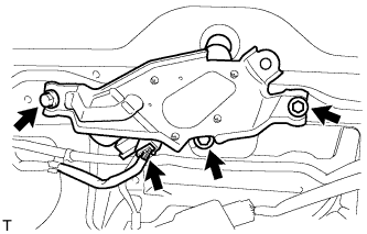
Temporarily install the rear wiper motor assembly with the 3 bolts.
-
Tighten the 3 bolts.
- Torque:
- 5.5 N*m { 56 kgf*cm, 49 in.*lbf }
-
Connect the connector.
-
-
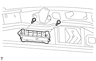
INSTALL REAR WIPER MOTOR GROMMET
-
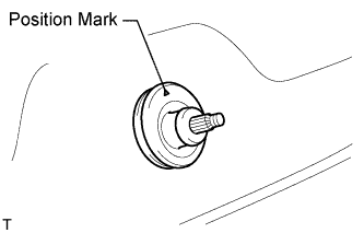
Install the rear wiper motor grommet with the position mark facing upward as shown in the illustration.
-
-
INSTALL REAR WIPER ARM
-
Operate the rear wiper, and stop the rear wiper motor at the automatic stop position.
-
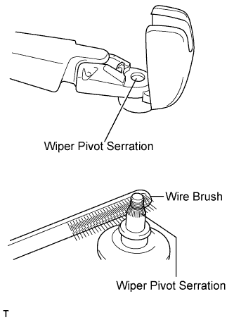
Clean the wiper pivot serration with a wire brush.
-
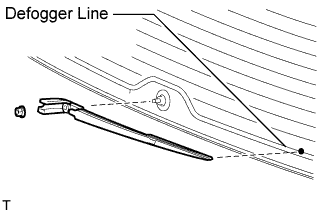
Set the head of the blade on the defogger line.
-
Install the rear wiper arm with the nut.
- Torque:
- 5.5 N*m { 56 kgf*cm, 49 in.*lbf }
-
Close the cover.
-
-
INSTALL POWER BACK DOOR SENSOR ASSEMBLY LH (w/ Power Back Door)
-
Attach the 2 clips to install the power back door sensor assembly LH.
-
Using a T25 "TORX" wrench, install the 6 screws.
-
Connect the connector.
-
-
INSTALL POWER BACK DOOR SENSOR ASSEMBLY RH (w/ Power Back Door)
Tech Tips
Use the same procedures described for the LH side.
-
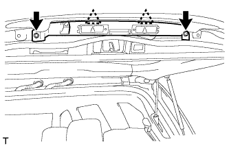
INSTALL REAR HEADER SPEAKER ASSEMBLY (for 19 Speakers)
-
Connect the connector.
-
Install the speaker with the 3 screws.
Note
Do not touch the cone part of the speaker.
-
-
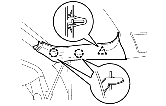
INSTALL BACK DOOR GARNISH
-
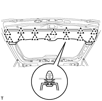
Attach the 14 clips to install the back door garnish.
-
-
INSTALL BACK DOOR SERVICE HOLE COVER RH (w/ Power Back Door)
-
When reusing the power back door rod:
-
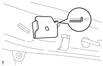
Install the back door stay plate.
-
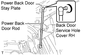
Pass the power back door rod through the hole of the back door service hole cover and install the rod with the bolt.
- Torque:
- 18 N*m { 184 kgf*cm, 13 ft.*lbf }
-
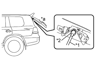
Text in Illustration *1 Power Back Door Rod *2 Hole of Back Door Service Hole Cover *a Back Door is Half-open Move the back door to a half-open position so that the hole in the center of the back door service hole cover is aligned lengthwise with the power back door rod.
-
Attach the 2 clips and install the back door service hole cover.
Note
If the back door is in a fully-open position, the power back door rod will interfere with the hole of the back door service hole cover, so do not perform this operation with the back door in a fully open position.
-
-
When installing a new power back door rod:
-
Install the back door stay plate.
-
Install the back door stay bolt.
- Torque:
- 18 N*m { 184 kgf*cm, 13 ft.*lbf }
-
Attach the 2 clips to install the service hole cover.
-
Attach the ball joints to install the power back door rod.
-
-
-
INSTALL BACK DOOR SIDE GARNISH LH
-
Attach the 3 clips to install the back door side garnish.
-
-
INSTALL BACK DOOR SIDE GARNISH RH
-
w/o Power Back Door:
Tech Tips
Use the same procedures described for the LH side.
-
w/ Power Back Door:
-
Attach the clip and 2 claws to install the back door side garnish.
-
-
-
INSTALL CENTER STOP LIGHT ASSEMBLY
-
Attach the 2 claws to install the stop light.
-
-
INSTALL CENTER BACK DOOR GARNISH
-
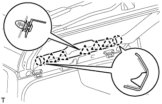
Attach the 5 clips and 2 claws to install the back door garnish.
-
-
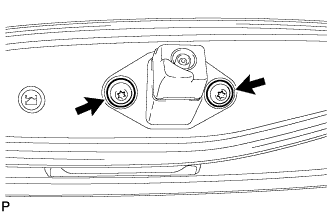
INSTALL LOWER BACK DOOR STOPPER CUSHION
-
Install the 2 back door stopper cushions with the 4 bolts.
-
-
INSTALL BACK DOOR GRIP
-
Install the back door grip with the 2 screws.
-
-
CONNECT CABLE TO NEGATIVE BATTERY TERMINAL
Note
When disconnecting the cable, some systems need to be initialized after the cable is reconnected Click here.
-
INSTALL ENGINE ROOM SIDE COVER LH
-
Install the engine room side cover LH with the 7 clips.
-
-
ADJUST REAR TELEVISION CAMERA ASSEMBLY
-
w/ Side Monitor System:
-
w/o Side Monitor System:
-