BACK DOOR DISASSEMBLY

-
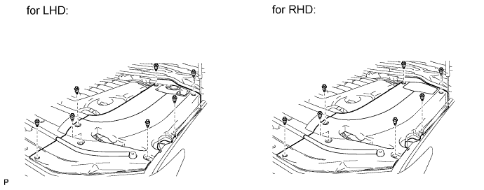
REMOVE ENGINE ROOM SIDE COVER LH
-
Remove the 7 clips and engine room side cover LH.
-
-
DISCONNECT CABLE FROM NEGATIVE BATTERY TERMINAL
Note
-
w/ Navigation System:
After the engine switch is turned off, the HDD navigation system requires approximately 6 minutes to record various types of memory and settings. As a result, after turning the engine switch off, wait 6 minutes or more before disconnecting the cable from the negative (-) battery terminal.
-
When disconnecting the cable, some systems need to be initialized after the cable is reconnected Click here.
-
-
REMOVE BACK DOOR GRIP
-
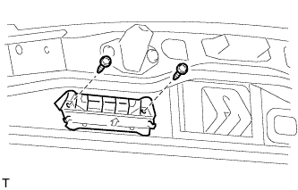
Remove the 2 screws and back door grip.
-
-
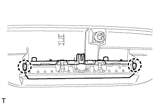
REMOVE LOWER BACK DOOR STOPPER CUSHION
-
Remove the 4 bolts and 2 lower back door stopper cushions.
-
-
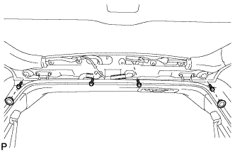
REMOVE CENTER BACK DOOR GARNISH
-
Detach the 5 clips and 2 claws, and remove the back door garnish.
-
-
REMOVE CENTER STOP LIGHT ASSEMBLY
-
Detach the 2 claws and remove the stop light.
-
-
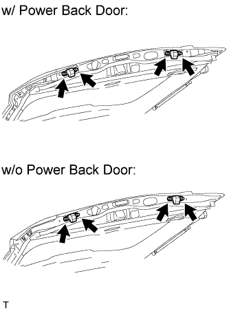
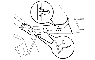
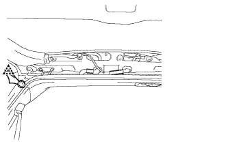
REMOVE BACK DOOR SIDE GARNISH LH
-
Detach the 3 clips and remove the back door side garnish.
-
-
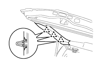
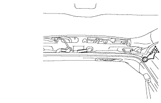
REMOVE BACK DOOR SIDE GARNISH RH
-
w/o Power Back Door:
Tech Tips
Use the same procedures described for the LH side.
-
w/ Power Back Door:
-
Detach the clip and 2 claws and remove the back door side garnish.
-
-
-
REMOVE BACK DOOR SERVICE HOLE COVER RH (w/ Power Back Door)
-
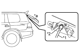
Text in Illustration *1 Power Back Door Rod *2 Hole of Back Door Service Hole Cover *a Back Door is Half-open Move the back door to a half-open position so that the hole in the center of the back door service hole cover is aligned lengthwise with the power back door rod.
-
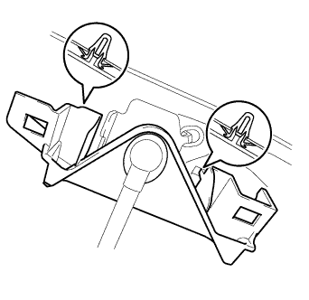
Detach the 2 clips and separate the back door service hole cover, passing the power back door rod through the hole of the back door service hole cover.
Note
If the back door is in a fully-open position, the power back door rod will interfere with the hole of the back door service hole cover, so do not perform this operation with the back door in a fully open position.
Tech Tips
If any of the clips have remained on the back door, remove the clips from the back door and install them to the back door service hole cover.
-
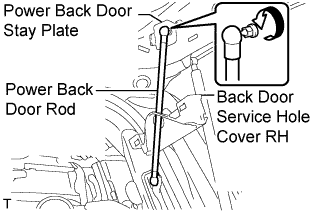
Remove the ball joint bolt, power back door rod and back door stay plate.
-
Remove the service hole cover from the power back door rod.
-
-
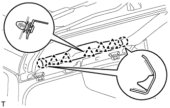
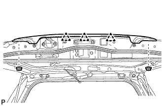
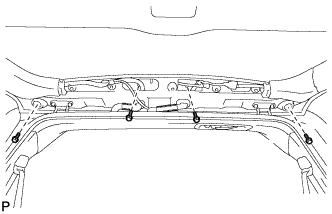
REMOVE BACK DOOR GARNISH
-
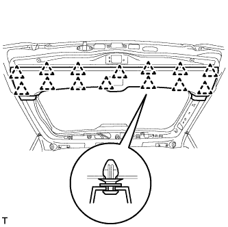
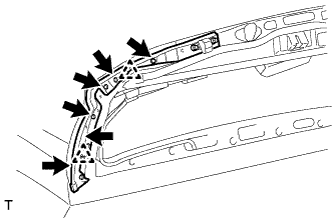
Using a screwdriver, detach the 14 clips and remove the back door garnish.
-
-
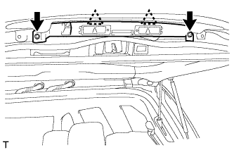
REMOVE REAR HEADER SPEAKER ASSEMBLY (for 19 Speakers)
-
Remove the 3 screws.
-
Disconnect the connector and remove the speaker.
Note
Do not touch the cone part of the speaker.
-
-
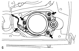
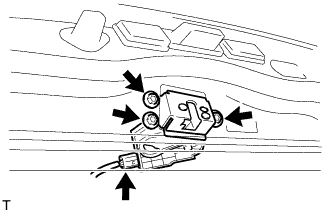
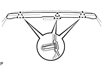
REMOVE POWER BACK DOOR SENSOR ASSEMBLY LH (w/ Power Back Door)
-
Disconnect the connector.
-
Using a T25 "TORX" wrench, remove the 6 screws.
-
Detach the 2 clips and remove the power back door sensor assembly LH.
-
-
REMOVE POWER BACK DOOR SENSOR ASSEMBLY RH (w/ Power Back Door)
Tech Tips
Use the same procedures described for the LH side.
-
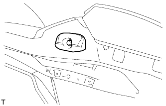
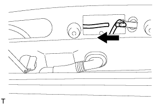
REMOVE REAR WIPER ARM
-
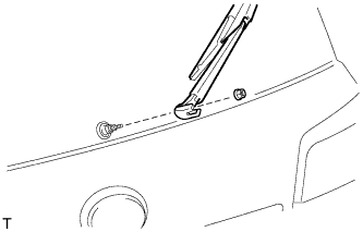
Open the cover.
-
Remove the nut and rear wiper arm.
-
-
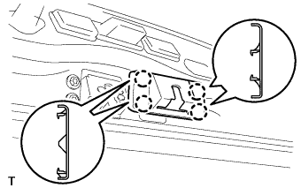
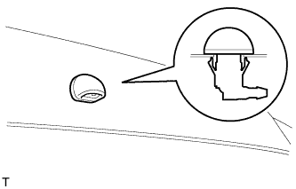
REMOVE REAR WIPER MOTOR GROMMET
-
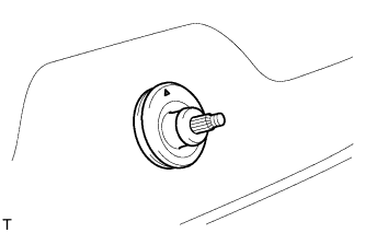
Remove the wiper motor grommet.
-
-
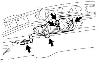
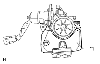
REMOVE REAR WIPER MOTOR ASSEMBLY
-
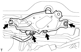
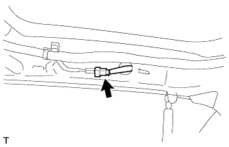
Disconnect the connector.
-
Remove the 3 bolts and rear wiper motor assembly.
-
-
REMOVE BACK DOOR LOCK COVER
-
Detach the 4 claws and remove the back door lock cover.
-
-
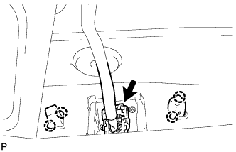
REMOVE BACK DOOR LOCK ASSEMBLY
-
w/o Power Back Door:
-
Disconnect the connector.
-
Remove the 3 bolts and back door lock.
-
-
w/ Power Back Door:
-
Disconnect the connector.
-
Remove the 4 bolts and back door lock.
-
-
-
REMOVE BACK DOOR LOCK PROTECTOR (w/ Power Back Door)
-
Remove the screw.
-
Text in Illustration *1 Protector (B) Detach the 7 claws and remove the protector (B).
-
Text in Illustration *1 Protector (A) Detach the 2 claws and remove the protector (A).
-
-
REMOVE SWITCH BEZEL (w/ Power Back Door)
-
Disconnect the connector.
-
Detach the 4 claws and remove the switch bezel.
-
-
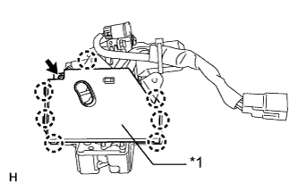
REMOVE BACK DOOR CONTROL SWITCH (w/ Power Back Door)
-
Detach the 2 claws and remove the door control switch.
-
-
REMOVE BACK DOOR GARNISH RETAINER SUB-ASSEMBLY
-
Using a T30 "TORX" socket wrench, detach the 2 clips and remove the 2 screws and garnish.
-
Disconnect the connector.
-
-
REMOVE LICENSE PLATE LIGHT ASSEMBLY
-
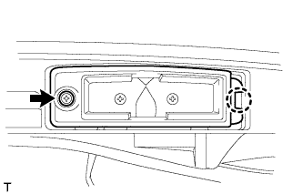
Remove the 2 screws.
-
Detach the 2 claws and remove the 2 lights.
-
-
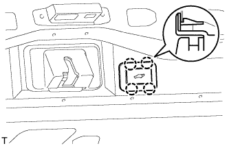
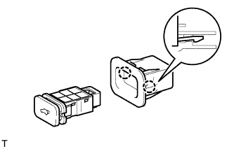
REMOVE BACK DOOR OPENER SWITCH ASSEMBLY
-
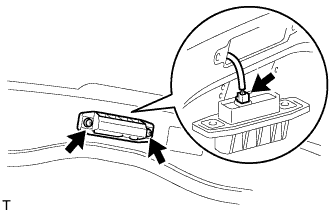
Remove the 2 screws.
-
Disconnect the connector and then remove the back door opener switch.
-
-
REMOVE REAR TELEVISION CAMERA ASSEMBLY
-
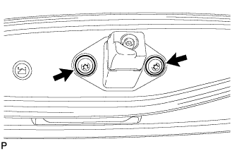
Using a T30 "TORX" socket wrench, remove the 2 screws.
-
Detach the 2 screws grommet and remove the rear television camera assembly.
-
Disconnect the connector.
-
-
REMOVE LIFT GATE WEATHERSTRIP
-
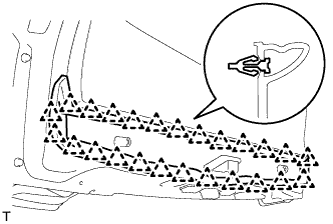
Detach the 25 clips and remove the lift gate weatherstrip.
Note
Do not pull strongly on the weatherstrip as it may be damaged.
-
-
REMOVE LOWER BACK DOOR STOPPER
-
Remove the bolt and lower back door stopper.
-
-
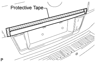
REMOVE BACK DOOR GARNISH SUB-ASSEMBLY OUTSIDE
-
Put protective tape around the back door garnish.
-
Remove the 2 nuts.
-
Detach the 3 clips and remove the garnish.
Tech Tips
Detach the clips from the backside of the garnish.
-
-
REMOVE BACK DOOR GLASS CHANNEL LH (w/o Power Back Door)
-
Using a clip remover, remove the clip.
-
Remove the back door glass channel LH.
-
-
REMOVE BACK DOOR GLASS CHANNEL RH (w/o Power Back Door)
-
Using a clip remover, remove the clip.
-
Remove the back door glass channel RH.
-
-
REMOVE REAR SPOILER SUB-ASSEMBLY
-
w/ Power Back Door:
Remove the 2 hole plugs and 4 bolts.
-
w/o Power Back Door:
Remove the 4 bolts.
-
Detach the 3 clips and remove the rear spoiler.
-
-
REMOVE REAR WASHER NOZZLE
-
Disconnect the hose.
-
Detach the 2 claws and remove the washer nozzle.
-
-
REMOVE BACK DOOR STAY ASSEMBLY LH
-
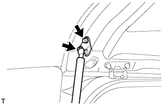
Remove the 2 bolts.
CAUTION:
Remove the door stay while supporting the back door with one hand.
-
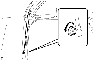
Remove the bolt and stay.
CAUTION:
Remove the door stay while supporting the back door with one hand.
-
-
REMOVE BACK DOOR STAY ASSEMBLY RH
Tech Tips
Use the same procedures described for the LH side.