FRONT DOOR DISASSEMBLY

Tech Tips
-
Use the same procedure for the RH and LH sides.
-
The procedure listed below is for the LH side.
-
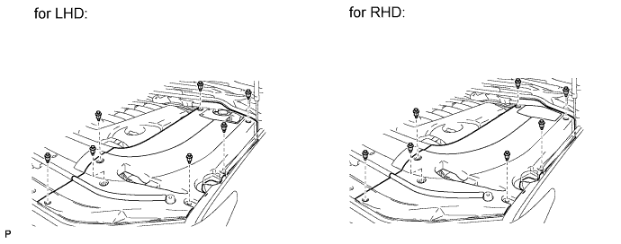
REMOVE ENGINE ROOM SIDE COVER LH
-
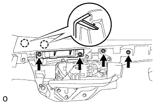
Remove the 7 clips and engine room side cover LH.
-
-
DISCONNECT CABLE FROM NEGATIVE BATTERY TERMINAL
CAUTION:
Wait at least 90 seconds after disconnecting the cable from the negative (-) battery terminal to disable the SRS system.
Note
-
w/ Navigation System:
After the engine switch is turned off, the HDD navigation system requires approximately 6 minutes to record various types of memory and settings. As a result, after turning the engine switch off, wait 6 minutes or more before disconnecting the cable from the negative (-) battery terminal.
-
When disconnecting the cable, some systems need to be initialized after the cable is reconnected Click here.
-
-
REMOVE FRONT DOOR OUTSIDE MOULDING SUB-ASSEMBLY LH
-
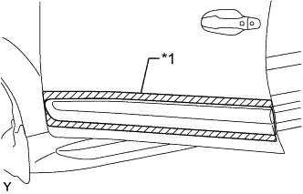
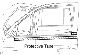
Text in Illustration *1 Protective Tape Put protective tape around the front door outside moulding sub-assembly LH.
-
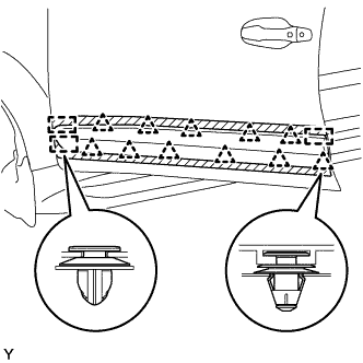
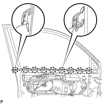
Using a moulding remover, detach the 3 clamps and 11 clips, and remove the front door outside moulding sub-assembly LH.
-
Remove any clips remaining on the door panel.
Note
Be careful not to allow any clips or pieces of clips to fall inside the door panel.
-
-
REMOVE FRONT LOWER DOOR FRAME BRACKET GARNISH LH
-
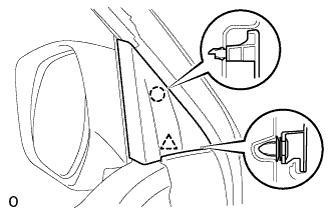
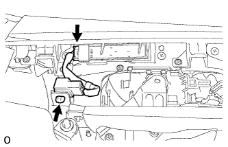
Detach the clip and claw, and remove the front lower door frame bracket garnish LH.
-
-
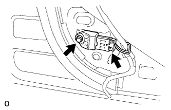
REMOVE COURTESY LIGHT ASSEMBLY
-
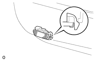
Detach the claw.
-
Remove the courtesy light and then disconnect the connector.
-
-
REMOVE FRONT DOOR INSIDE HANDLE BEZEL PLUG LH
-
Text in Illustration *1 Protective Tape Using a screwdriver, detach the 3 claws and remove the front door inside handle bezel plug LH.
Tech Tips
Tape the screwdriver tip before use.
-
-
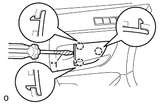
REMOVE FRONT UPPER ARMREST BASE PANEL LH
-
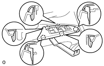
Using a moulding remover, detach the 5 claws.
-
Disconnect the connector and remove the front upper armrest base panel LH and multiplex network master switch assembly.
-
-
REMOVE MULTIPLEX NETWORK MASTER SWITCH ASSEMBLY
-
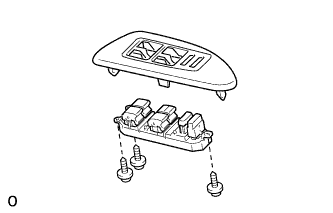
Remove the 3 screws and master switch.
-
-
REMOVE FRONT LOWER DOOR ARMREST BASE PANEL LH
-
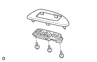
Remove the 3 screws and front lower door armrest base panel LH.
-
-
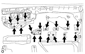
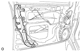
REMOVE FRONT DOOR TRIM BOARD SUB-ASSEMBLY LH
-
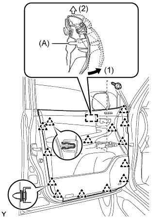
Remove the 2 screws.
-
Detach the 14 clips.
-
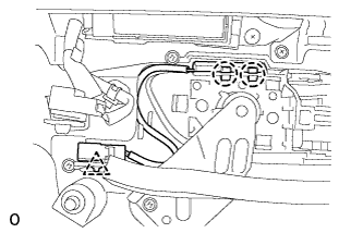
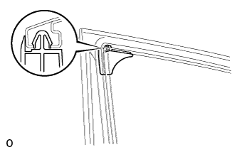
Remove the front inner door glass weatherstrip LH together with the front door trim board sub-assembly LH by pulling them upward in the order shown in the illustration.
Tech Tips
Make sure that the pin labeled A in the illustration is detached from the door panel.
-
Disconnect the connector.
-
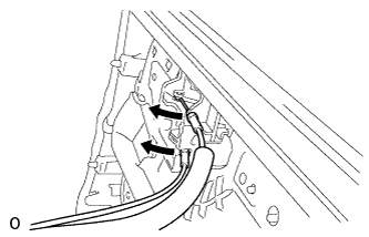
Disconnect the 2 cables from the front door inside handle sub-assembly LH.
-
-
REMOVE FRONT INNER DOOR GLASS WEATHERSTRIP LH
-
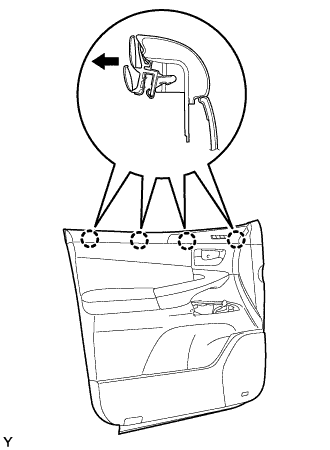
Detach the 4 clips and remove the front inner door glass weatherstrip LH from the front door trim board sub-assembly LH.
Note
-
Squeeze the metal clip to remove it.
-
The metal clip may be deformed if it is forcibly pulled.
-
-
-
REMOVE FRONT DOOR INSIDE HANDLE ILLUMINATION LIGHT ASSEMBLY LH
-
Detach the 2 claws and clamp, and remove the light.
-
-
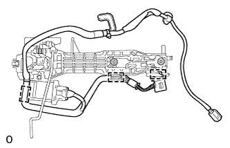
REMOVE FRONT DOOR WIRING SUB-ASSEMBLY RH
-
Disconnect the connector.
-
Detach the clamp and remove the front door wiring sub-assembly RH.
-
-
REMOVE SEAT MEMORY SWITCH
-
Remove the 4 screws.
-
Detach the 2 claws and remove the front door trim ornament.
-
Detach the 4 claws and remove the seat memory switch.
-
-
REMOVE FRONT DOOR INSIDE HANDLE SUB-ASSEMBLY LH
-
Remove the 17 screws and front door armrest assembly LH.
-
Remove the 5 screws and front door inside handle sub-assembly LH.
-
-
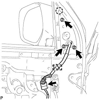
REMOVE OUTER REAR VIEW MIRROR ASSEMBLY LH
-
Disconnect the connector.
-
Detach the clamp.
-
Remove the 3 nuts.
-
Detach the claw and remove the mirror.
-
-
REMOVE OUTER MIRROR CONTROL ECU ASSEMBLY
-
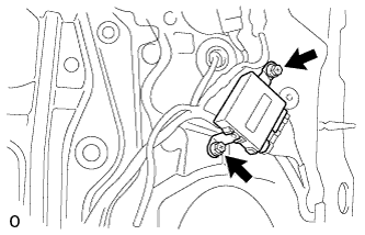
Disconnect the 2 connectors.
-
Remove the 2 screws and outer mirror control ECU assembly.
-
-
REMOVE FRONT NO. 1 DOOR STIFFENER CUSHION
-
Remove the screw and front No. 1 door stiffener cushion.
-
-
REMOVE DOOR TRIM COVER LH
-
Using a clip remover, detach the 7 clips and remove the door trim cover LH.
-
-
REMOVE FRONT NO. 1 SPEAKER ASSEMBLY
-
Disconnect the speaker connector.
-
Remove the 4 screws and speaker.
Note
Do not touch the cone part of the speaker.

-
-
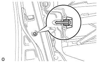
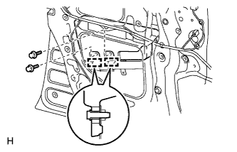
REMOVE SIDE AIRBAG SENSOR ASSEMBLY LH
-
Disconnect the connector.
-
Remove the bolt and side airbag sensor.
-
-
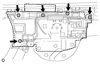
REMOVE FRONT DOOR SERVICE HOLE COVER LH
-
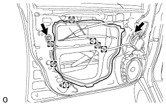
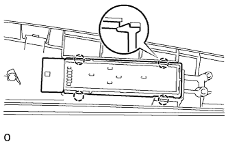
Using a clip remover, detach the 7 clamps.
-
Remove the bolt and disconnect the 2 connectors.
-
Remove the front door service hole cover LH.
Tech Tips
Remove the remaining tape on the door.
-
-
REMOVE FRONT DOOR GLASS SUB-ASSEMBLY LH
-
for Driver Side:
Temporarily install the multiplex network master switch assembly.
-
for Passenger Side:
Temporarily install the power window regulator switch assembly.
-
Connect the cable to the negative (-) battery terminal.
-
Move the door glass until the bolts appear in the service holes.
-
Disconnect the cable from the negative (-) battery terminal.
-
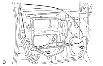
Remove the 2 bolts.
Note
Be careful when removing the bolts as the glass may fall and become damaged.
-
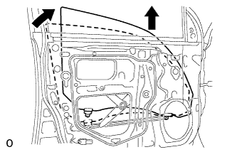
Remove the door glass in the direction indicated by the arrows in the illustration.
Tech Tips
Remove the glass upward.
Note
Be careful not to damage the glass.
-
for Driver Side:
Remove the multiplex network master switch assembly.
-
for Passenger Side:
Remove the power window regulator switch assembly.
-
-
REMOVE FRONT DOOR GLASS RUN LH
-
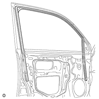
Remove the front door glass run LH.
-
-
REMOVE FRONT DOOR REAR LOWER FRAME SUB-ASSEMBLY LH
-
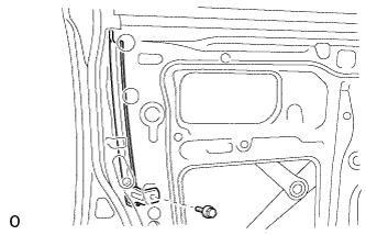
Remove the bolt and front door rear lower frame sub-assembly LH.
-
-
REMOVE LOWER DOOR FRAME GARNISH LH
-
Detach the clip and remove the lower door frame garnish LH.
-
-
REMOVE FRONT DOOR BELT MOULDING ASSEMBLY LH
-
Put protective tape around the belt moulding.
-
Detach the claw and remove the belt moulding.
-
-
REMOVE FRONT DOOR REAR WINDOW FRAME MOULDING LH
-
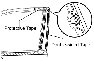
Put protective tape around the window frame moulding.
-
Detach the clip and remove the double-sided tape to remove the window frame moulding.
-
-
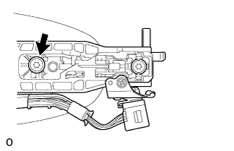
REMOVE FRONT DOOR WINDOW REGULATOR SUB-ASSEMBLY LH
-
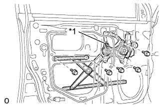
Text in Illustration *1 Temporary Bolt Loosen the temporary bolt.
-
Remove the 5 bolts.
Note
Be careful when removing the bolts as the front door window regulator sub-assembly LH may fall and become damaged.
-
Remove the front door window regulator sub-assembly LH and the front power window regulator motor assembly as a unit.
Tech Tips
Remove the window regulator through the service hole.
-
Remove the temporary bolt from the front door window regulator sub-assembly LH.
-
-
REMOVE FRONT POWER WINDOW REGULATOR MOTOR ASSEMBLY LH
-
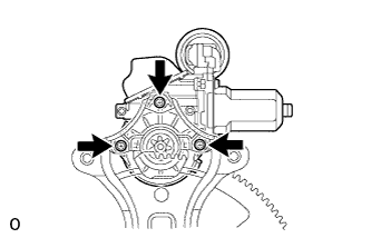
Using a T25 "TORX" driver, remove the 3 screws and motor.
Note
Be careful when removing the screws as the motor may fall and become damaged.
-
-
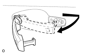
REMOVE FRONT DOOR OUTSIDE HANDLE COVER LH
-
Remove the hole plug.
-
Using a T30 "TORX" wrench, loosen the screw and remove the front door outside handle cover LH with the door lock cylinder installed.
-
Detach the 2 claws and remove the front door outside handle cover LH.
-
-
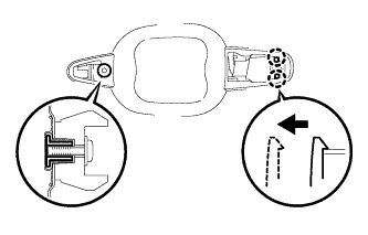
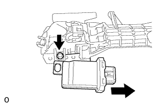
REMOVE FRONT DOOR OUTSIDE HANDLE ASSEMBLY LH
-
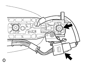
Disconnect the connector.
-
Using a T30 "TORX" wrench, loosen the screw.
-
Remove the front door outside handle assembly LH by sliding and pulling it in the direction indicated by the arrow in the illustration.
Note
If the release plate is not pulled and held when removing the front door outside handle assembly LH, the release plate will interfere with the front door outside handle assembly LH and become damaged.
-
-
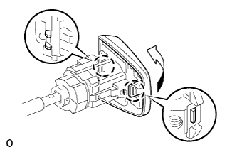
REMOVE FRONT DOOR FRONT OUTSIDE HANDLE PAD LH
-
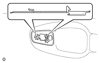
Detach the 3 claws and remove the front door front outside handle pad LH.
-
-
REMOVE FRONT DOOR REAR OUTSIDE HANDLE PAD LH
-
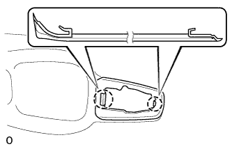
Detach the 2 claws and remove the front door rear outside handle pad LH.
-
-
REMOVE FRONT DOOR LOCK ASSEMBLY LH
-
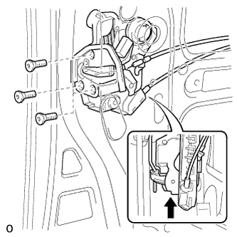
Using a T30 "TORX" wrench, remove the 3 screws and door lock.
Tech Tips
Remove the door lock through the service hole.
Note
Be careful when removing the screws as the door lock may fall and become damaged.
-
-
REMOVE FRONT DOOR LOCK REMOTE CONTROL CABLE ASSEMBLY LH
-
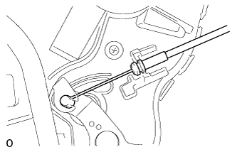
Remove the front door lock remote control cable assembly LH.
-
-
REMOVE FRONT DOOR INSIDE LOCKING CABLE ASSEMBLY LH
-
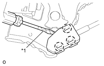
Text in Illustration *1 Protective Tape Using a screwdriver, detach the 3 claws.
Tech Tips
Tape the screwdriver tip before use.
-
Remove the front door inside locking cable assembly LH.
-
-
REMOVE FRONT DOOR OUTSIDE HANDLE FRAME SUB-ASSEMBLY LH
-
Using a T30 "TORX" wrench, loosen the screw.
-
Detach the 2 claws. Slide the front door outside handle frame sub-assembly LH and No. 2 electrical key wire harness to remove them.
Tech Tips
Remove the front door outside handle frame sub-assembly LH through the service hole.
-
-
REMOVE NO. 2 ELECTRICAL KEY WIRE HARNESS
-
Disconnect the connector.
-
Detach the 3 clamps and remove the No. 2 electrical key wire harness from the front door outside handle frame sub-assembly.
-
-
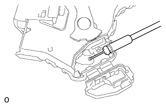
REMOVE FRONT DOOR LOCK OPEN ROD LH
-
Remove the front door lock open rod LH.
-
-
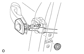
REMOVE DOOR ELECTRICAL KEY OSCILLATOR
-
Remove the screw and door electrical key oscillator.
-
-
REMOVE FRONT NO. 2 DOOR STIFFENER CUSHION
-
Remove the 2 bolts.
-
Detach the 2 clamps and remove the front No. 2 door stiffener cushion.
-
-
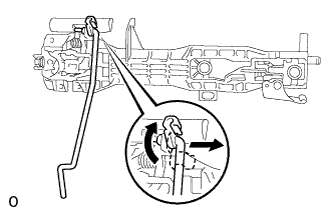
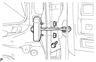
REMOVE FRONT DOOR CHECK ASSEMBLY LH
-
Remove the bolt, 2 nuts and front door check assembly LH.
Note
Be careful when removing the bolt and nuts as the front door check assembly LH may fall and become damaged.
Tech Tips
Remove the front door check assembly LH through the service hole.
-
-
REMOVE FRONT DOOR WEATHERSTRIP LH
-
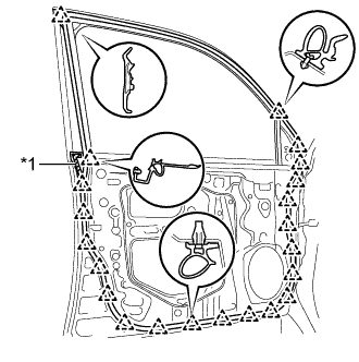
Text in Illustration *1 Double-sided Tape Using a clip remover, detach the 22 clips and remove the front door weatherstrip LH.
Tech Tips
If clips are damaged during removal, replace them.
-