TAIL GATE CLOSER SYSTEM Tail Gate does not Open with Back Door Remote Control
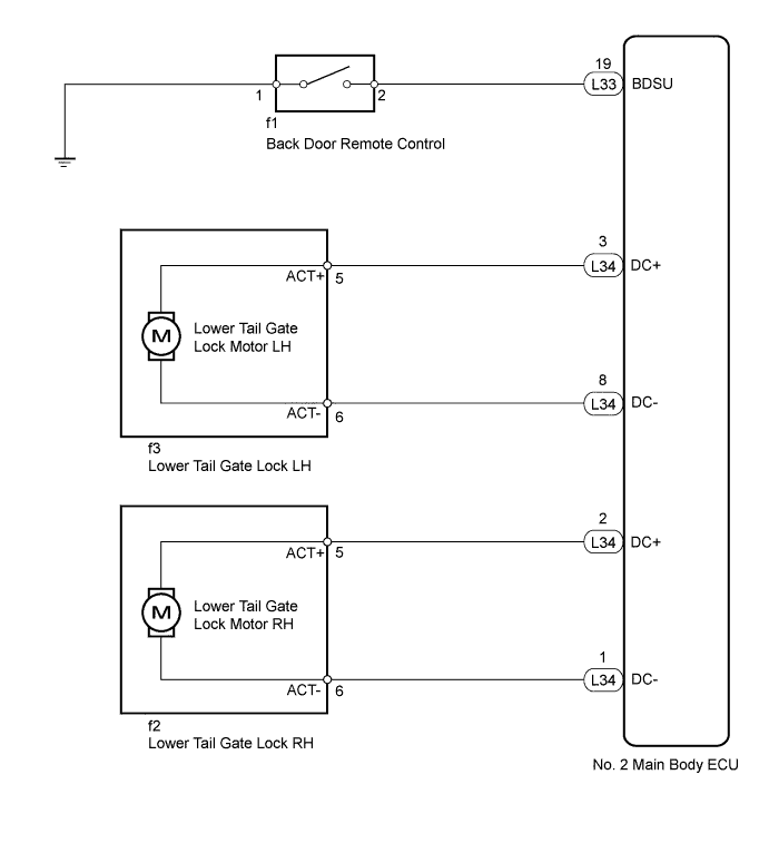
WIRING DIAGRAM
INSPECTION PROCEDURE
PROCEDURE
-
PERFORM ACTIVE TEST USING INTELLIGENT TESTER (LOWER TAIL GATE LOCK)
-
Select the Active Test, use the intelligent tester to generate a control command, and check that the lower tail gate lock operates.
Body No. 4 Tester Display Test Part Control Range Diagnostic Note Tail Gate Panel Open Lower tail gate lock ON or OFF The back door must be open. OK Lower tail gate lock operates normally.
NG 
INSPECT LOWER TAIL GATE LOCK ASSEMBLY Click here
OK 
-
-
READ VALUE USING INTELLIGENT TESTER (BACK DOOR REMOTE CONTROL)
-
Check the Data List for proper functioning of the back door remote control.
Body No. 4 Tester Display Measurement Item/Range Normal Condition Diagnostic Note Handle Switch of tail gate panel Back door remote control signal/ON or OFF ON: Back door remote control pulled
OFF: Back door remote control free
- OK The display is as specified in the normal condition.
NG
INSPECT BACK DOOR REMOTE CONTROL Click here
OK 
REPLACE NO. 2 MAIN BODY ECU Click here
-
-
INSPECT LOWER TAIL GATE LOCK ASSEMBLY
-
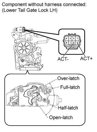
for LH:
-
Remove the lower tail gate lock LH Click here.
-
Set the lower tail gate lock LH to the full-latch position.
-
Apply battery voltage and check the operation of the lower tail gate lock motor LH.
OK Measurement Condition Specified Condition Battery positive (+) → Terminal 6 (ACT-)
Battery negative (-) → Terminal 5 (ACT+)
Latch turns to open-latch position
-
-
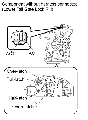
for RH:
-
Remove the lower tail gate lock RH Click here.
-
Set the lower tail gate lock RH to the full-latch position.
-
Apply battery voltage and check the operation of the lower tail gate lock motor RH.
OK Measurement Condition Specified Condition Battery positive (+) → Terminal 6 (ACT-)
Battery negative (-) → Terminal 5 (ACT+)
Latch turns to open-latch position Result Result Proceed to OK A NG (for LH) B NG (for RH) C
-
B 
REPLACE LOWER TAIL GATE LOCK ASSEMBLY LH Click here
C
REPLACE LOWER TAIL GATE LOCK ASSEMBLY RH Click here
A
-
-
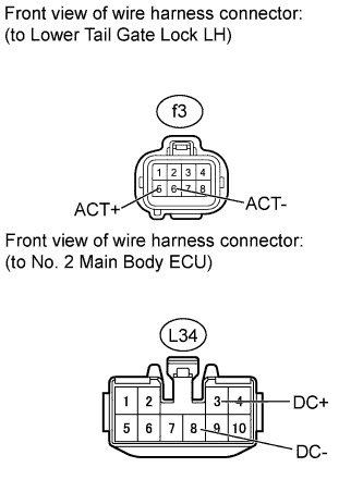
CHECK HARNESS AND CONNECTOR (LOCK - ECU)
-
for LH:
-
Disconnect the f3 lock connector.
-
Disconnect the L34 ECU connector.
-
Measure the resistance according to the value(s) in the table below.
Standard Resistance Tester Connection Condition Specified Condition f3-5 (ACT+) - L34-3 (DC+) Always Below 1 Ω f3-6 (ACT-) - L34-8 (DC-) Always Below 1 Ω f3-5 (ACT+) - Body ground Always 10 kΩ or higher f3-6 (ACT-) - Body ground Always 10 kΩ or higher
-
-
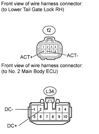
for RH:
-
Disconnect the f2 lock connector.
-
Disconnect the L34 ECU connector.
-
Measure the resistance according to the value(s) in the table below.
Standard Resistance Tester Connection Condition Specified Condition f2-5 (ACT+) - L34-2 (DC+) Always Below 1 Ω f2-6 (ACT-) - L34-1 (DC-) Always Below 1 Ω f2-5 (ACT+) - Body ground Always 10 kΩ or higher f2-6 (ACT-) - Body ground Always 10 kΩ or higher
-
NG
REPAIR OR REPLACE HARNESS OR CONNECTOR
OK
REPLACE NO. 2 MAIN BODY ECU Click here
-
-
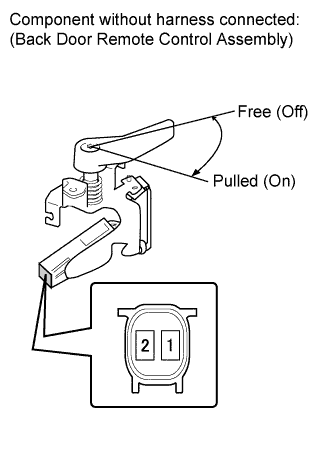
INSPECT BACK DOOR REMOTE CONTROL
-
Remove the back door remote control Click here.
-
Measure the resistance according to the value(s) in the table below.
Standard Resistance Tester Connection Switch Condition Specified Condition 1 - 2 Back door remote control is pulled (on) Below 1 Ω 1 - 2 Back door remote control is free (off) 10 kΩ or higher
NG
REPLACE BACK DOOR REMOTE CONTROL ASSEMBLY Click here
OK
-
-
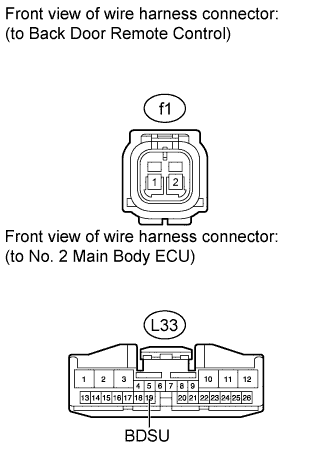
CHECK HARNESS AND CONNECTOR (CONTROL - ECU AND BODY GROUND)
-
Disconnect the f1 control connector.
-
Disconnect the L33 ECU connector.
-
Measure the resistance according to the value(s) in the table below.
Standard Resistance Tester Connection Condition Specified Condition f1-2 - L33-19 (BDSU) Always Below 1 Ω f1-1 - Body ground Always Below 1 Ω f1-2 - Body ground Always 10 kΩ or higher
NG
REPAIR OR REPLACE HARNESS OR CONNECTOR
OK
REPLACE NO. 2 MAIN BODY ECU Click here
-