POWER BACK DOOR SYSTEM Power Back Door Opener / Closer Switch Circuit
DESCRIPTION
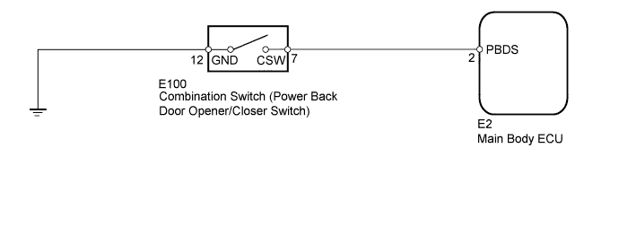
The combination switch (power back door opener/closer switch) only turns on while the switch is being pressed, and turns off when the switch is released.
When the switch is on, a power back door operation request signal is input to the main body ECU to operate the back door.
WIRING DIAGRAM
INSPECTION PROCEDURE
PROCEDURE
-
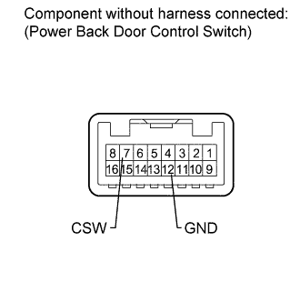
READ VALUE USING INTELLIGENT TESTER (POWER BACK DOOR CONTROL SWITCH)
-
Check the Data List for proper functioning of the power back door opener/closer switch.
Main Body Tester Display Measurement Item/Range Normal Condition Diagnostic Note Back Door Open SW Power back door opener/closer switch signal/ON or OFF ON: Power back door opener/closer switch on
OFF: Power back door opener/closer switch off
- OK The display is as specified in the normal condition.
NG 
INSPECT COMBINATION SWITCH ASSEMBLY (POWER BACK DOOR OPENER/CLOSER SWITCH) Click here
OK 
REPLACE MAIN BODY ECU
-
-
INSPECT COMBINATION SWITCH ASSEMBLY (POWER BACK DOOR OPENER/CLOSER SWITCH)
-
Remove the combination switch Click here.
-
Measure the resistance according to the value(s) in the table below.
Standard Resistance Tester Connection Switch Condition Specified Condition 7 (CSW) - 12 (GND) Power back door opener/closer switch is pushed (on) Below 1 Ω 7 (CSW) - 12 (GND) Power back door opener/closer switch is free (off) 10 kΩ or higher
NG 
REPLACE COMBINATION SWITCH ASSEMBLY Click here
OK 
-
-
CHECK HARNESS AND CONNECTOR (SWITCH - ECU AND BODY GROUND)
-
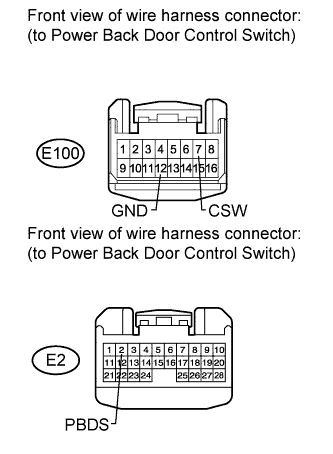
Disconnect the E100 switch connector.
-
Disconnect the E2 ECU connector.
-
Measure the resistance according to the value(s) in the table below.
Standard Resistance Tester Connection Condition Specified Condition E100-7 (CSW) - E2-2 (PBDS) Always Below 1 Ω E100-12 (GND) - Body ground Always Below 1 Ω E100-7 (CSW) - Body ground) Always 10 kΩ or higher
NG
REPAIR OR REPLACE HARNESS OR CONNECTOR
OK
REPLACE MAIN BODY ECU
-