POWER BACK DOOR SYSTEM Back Door Lock Motor Circuit
DESCRIPTION
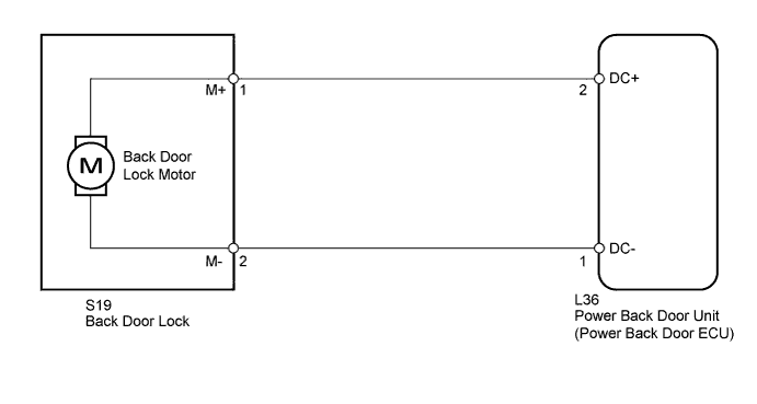
The back door lock motor is built into the back door lock. The power back door unit (power back door ECU) controls the back door lock motor to open/close the back door. This ECU applies current to terminals 2 and 1 to operate the motor to close the door. It reverses the direction of the current to operate the motor to open the door.
WIRING DIAGRAM
INSPECTION PROCEDURE
PROCEDURE
-
INSPECT BACK DOOR LOCK ASSEMBLY
-
Remove the back door lock Click here.
-
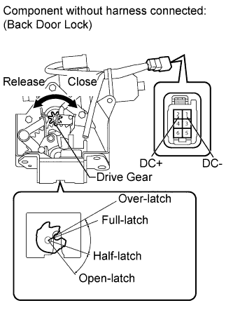
Set the back door lock to the half-latch position.
-
Apply battery voltage and check operation of the door lock motor.
OK Measurement Condition Specified Condition Battery positive (+) → Terminal 1 (DC-)
Battery negative (-) → Terminal 2 (DC+)
Latch turns to over-latch position -
Set the back door lock to the full-latch position.
-
Apply battery voltage and check operation of the door lock motor.
OK Measurement Condition Specified Condition Battery positive (+) → Terminal 2 (DC+)
Battery negative (-) → Terminal 1 (DC-)
Latch turns to open-latch position
NG 
REPLACE BACK DOOR LOCK ASSEMBLY Click here
OK 
-
-
CHECK HARNESS AND CONNECTOR (LOCK - UNIT)
-
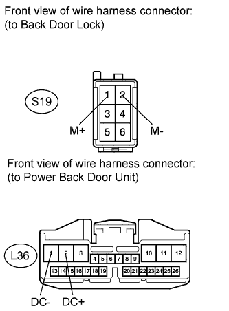
Disconnect the S19 door lock connector.
-
Disconnect the L36 unit connector.
-
Measure the resistance according to the value(s) in the table below.
Standard Resistance Tester Connection Condition Specified Condition S19-1 (M+) - L36-2 (DC+) Always Below 1 Ω S19-2 (M-) - L36-1 (DC-) Always Below 1 Ω S19-1 (M+) - Body ground Always 10 kΩ or higher S19-2 (M-) - Body ground Always 10 kΩ or higher
NG
REPAIR OR REPLACE HARNESS OR CONNECTOR
OK 
REPLACE POWER BACK DOOR UNIT ASSEMBLY Click here
-