POWER BACK DOOR SYSTEM Power Back Door Warning Buzzer Circuit
DESCRIPTION
The power back door unit (power back door ECU) receives the power back door ON/OFF switch signal to sound the power back door warning buzzer.
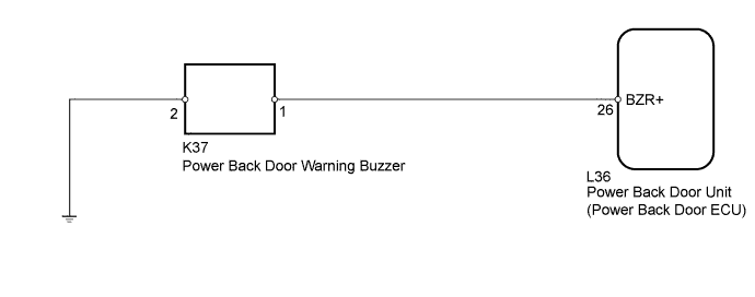
WIRING DIAGRAM
INSPECTION PROCEDURE
PROCEDURE
-
PERFORM ACTIVE TEST USING INTELLIGENT TESTER (POWER BACK DOOR WARNING BUZZER)
-
Select the Active Test, use the intelligent tester to generate a control command, and check that the power back door warning buzzer sounds.
Back Door Tester Display Test Part Control Range Diagnostic Note PBD Buzzer Operate warning buzzer ON/OFF - OK Power back door warning buzzer sounds normally.
NG 
CHECK HARNESS AND CONNECTOR (BUZZER - UNIT AND BODY GROUND) Click here
OK 
REPLACE POWER BACK DOOR UNIT ASSEMBLY Click here
-
-
CHECK HARNESS AND CONNECTOR (BUZZER - UNIT AND BODY GROUND)
-
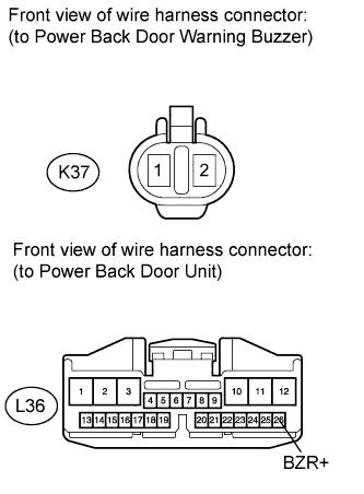
Disconnect the K37 buzzer connector.
-
Disconnect the L36 ECU connector.
-
Measure the resistance according to the value(s) in the table below.
Standard Resistance Tester Connection Condition Specified Condition K37-1 - L36-26 (BZR+) Always Below 1 Ω K37-2 - Body ground Always Below 1 Ω K37-1 - Body ground Always 10 kΩ or higher
NG 
REPAIR OR REPLACE HARNESS OR CONNECTOR
OK 
-
-
REPLACE POWER BACK DOOR WARNING BUZZER
-
Replace power back door warning buzzer Click here.
NEXT
-
-
PERFORM ACTIVE TEST USING INTELLIGENT TESTER (POWER BACK DOOR WARNING BUZZER)
-
Select the Active Test, use the intelligent tester to generate a control command, and check that the power back door warning buzzer sounds.
Back Door Tester Display Test Part Control Range Diagnostic Note PBD Buzzer Operate warning buzzer ON/OFF - OK Power back door warning buzzer sounds normally.
NG
REPLACE POWER BACK DOOR UNIT ASSEMBLY Click here
OK
END (POWER BACK DOOR WARNING BUZZER IS DEFECTIVE)
-