POWER WINDOW REGULATOR MOTOR (for Front Door) REMOVAL

Tech Tips
-
Use the same procedures for the LH side and RH side.
-
The procedures listed below are for the LH side.
-
DISCONNECT CABLE FROM NEGATIVE BATTERY TERMINAL
CAUTION:
Wait at least 90 seconds after disconnecting the cable from the negative (-) battery terminal to disable the SRS system.
Note
When disconnecting the cable, some systems need to be initialized after the cable is reconnected Click here.
-
REMOVE FRONT LOWER DOOR FRAME BRACKET GARNISH
-
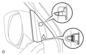
Detach the clip and claw, and remove the front lower door frame bracket garnish LH.
-
-
REMOVE FRONT DOOR INSIDE HANDLE BEZEL PLUG
-
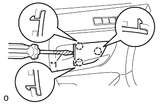
Text in Illustration *1 Protective Tape Using a screwdriver, detach the 3 claws and remove the front door inside handle bezel plug LH.
Tech Tips
Tape the screwdriver tip before use.
-
-
REMOVE FRONT UPPER ARMREST BASE PANEL
-
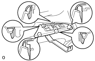
Using a moulding remover, detach the 5 claws.
-
Disconnect the connector and remove the front upper armrest base panel LH and multiplex network master switch assembly.
-
-
REMOVE FRONT DOOR TRIM BOARD SUB-ASSEMBLY
-
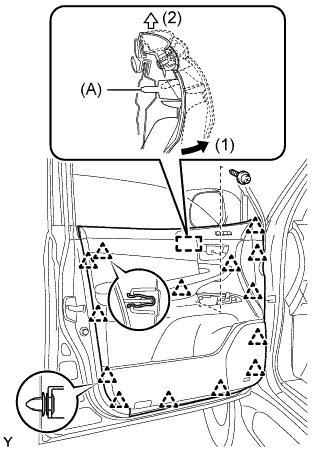
Remove the 2 screws.
-
Detach the 14 clips.
-
Remove the front inner door glass weatherstrip LH together with the front door trim board sub-assembly LH by pulling them upward in the order shown in the illustration.
Tech Tips
Make sure that the pin labeled A in the illustration is detached from the door panel.
-
Disconnect the connector.
-
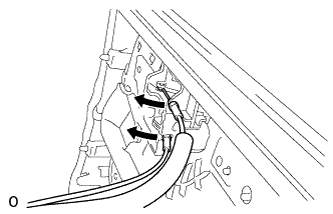
Disconnect the 2 cables from the front door inside handle sub-assembly LH.
-
-
REMOVE FRONT NO. 1 SPEAKER ASSEMBLY
-
Disconnect the speaker connector.
-
Remove the 4 screws and speaker.
Note
Do not touch the cone part of the speaker.

-
-
REMOVE FRONT DOOR SERVICE HOLE COVER
-
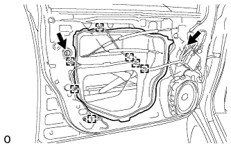
Using a clip remover, detach the 7 clamps.
-
Remove the bolt and disconnect the 2 connectors.
-
Remove the front door service hole cover LH.
Tech Tips
Remove the remaining tape on the door.
-
-
REMOVE FRONT DOOR GLASS SUB-ASSEMBLY
-
for Driver Side:
Temporarily install the multiplex network master switch assembly.
-
for Passenger Side:
Temporarily install the power window regulator switch assembly.
-
Connect the cable to the negative (-) battery terminal.
-
Move the door glass until the bolts appear in the service holes.
-
Disconnect the cable from the negative (-) battery terminal.
-
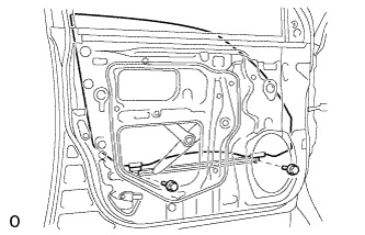
Remove the 2 bolts.
Note
Be careful when removing the bolts as the glass may fall and become damaged.
-
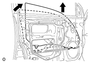
Remove the door glass in the direction indicated by the arrows in the illustration.
Tech Tips
Remove the glass upward.
Note
Be careful not to damage the glass.
-
for Driver Side:
Remove the multiplex network master switch assembly.
-
for Passenger Side:
Remove the power window regulator switch assembly.
-
-
REMOVE FRONT DOOR WINDOW REGULATOR SUB-ASSEMBLY
-
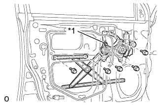
Text in Illustration *1 Temporary Bolt Loosen the temporary bolt.
-
Remove the 5 bolts.
Note
Be careful when removing the bolts as the front door window regulator sub-assembly LH may fall and become damaged.
-
Remove the front door window regulator sub-assembly LH and the front power window regulator motor assembly as a unit.
Tech Tips
Remove the window regulator through the service hole.
-
Remove the temporary bolt from the front door window regulator sub-assembly LH.
-
-
REMOVE FRONT POWER WINDOW REGULATOR MOTOR ASSEMBLY
-
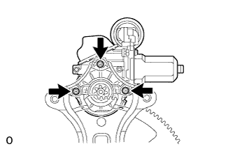
Using a T25 "TORX" driver, remove the 3 screws and motor.
Note
Be careful when removing the screws as the motor may fall and become damaged.
-