DYNAMIC RADAR CRUISE CONTROL SYSTEM TERMINALS OF ECU

-
CHECK ECM
Tech Tips
As the ECM connector is a waterproof connector, it is not possible to check the voltage of each terminal or check the waveform with an oscilloscope while the ECM is installed in the vehicle.
-
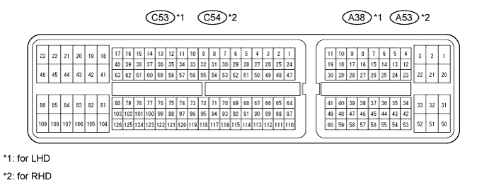
Disconnect the A38*1 and C53*1 or A53*2 and C54*2 ECM connectors.
-
*1: for LHD
-
*2: for RHD
-
-
Measure the voltage and resistance according to the value(s) in the table below.
Terminal No. (Symbol) Wiring Color Terminal Description Condition Specified Condition A38*1-16 (TC) - Body ground
A53*2-16 (TC) - Body ground
V-W - Body ground Terminal TC of DLC3 Engine switch on (IG) 11 to 14 V Engine switch off Below 1 V C53*1-81 (E1) - Body ground
C54*2-81 (E1) - Body ground
W-B - Body ground ECM ground Always Below 1 Ω C53*1-27 (D) - Body ground
C54*2-27 (D) - Body ground
G - Body ground Park/neutral position switch signal Engine switch on (IG)
Shift lever in D
11 to 14 V Engine switch on (IG)
Shift lever not in D
Below 1 V A38*1-38 (SFTU) - Body ground
A53*2-38 (SFTU) - Body ground
Y - Body ground Park/neutral position switch signal Engine switch on (IG)
Shift lever in S
Below 1 Ω Engine switch on (IG)
Shift lever in +
10 kΩ or higher A38*1-25 (S) - Body ground
A53*2-25 (S) - Body ground
W - Body ground Park/neutral position switch signal Engine switch on (IG)
Shift lever in S
11 to 14 V Engine switch on (IG)
Shift lever not in S
Below 1 V A38*1-27 (SFTD) - Body ground
A53*2-27 (SFTD) - Body ground
L - Body ground Park/neutral position switch signal Engine switch on (IG)
Shift lever in S
10 kΩ or higher Engine switch on (IG)
Shift lever in -
Below 1 Ω A38*1-36 (STP) - Body ground
A53*2-36 (STP) - Body ground
R - Body ground Stop light signal Engine switch on (IG)
Brake pedal depressed
11 to 14 V Engine switch on (IG)
Brake pedal released
Below 1 V A38*1-35 (ST1-) - Body ground
A53*2-35 (ST1-) - Body ground
R-W - Body ground Stop light signal (opposite to STP terminal) Engine switch on (IG)
Brake pedal depressed
Below 1 V Engine switch on (IG)
Brake pedal released
11 to 14 V A38*1-45 (CCS) - Body ground
A53*2-45 (CCS) - Body ground
L - Body ground Cruise control main switch signal Engine switch on (IG)
Main switch off
1 MΩ or higher Engine switch on (IG)
CANCEL switch held on
1510 to 1570 Ω Engine switch on (IG)
-SET switch held on
620 to 640 Ω Engine switch on (IG)
+RES switch held on
235 to 245 Ω Engine switch on (IG)
Main switch on
Below 2.5 Ω A38*1-37 (CCHG) - Body ground
A53*2-37 (CCHG) - Body ground
P-B - Body ground Distance control switch signal Engine switch on (IG)
Main switch on
MODE switch held on
Below 1 V Engine switch on (IG)
Main switch on
MODE switch off
11 to 14 V
-
*1: for LHD
-
*2: for RHD
If the result is not as specified, there may be a malfunction on the wire harness side.
-
-
-
CHECK DISTANCE CONTROL ECU

-
Disconnect the E86 distance control ECU connector.
-
Measure the voltage and resistance according to the value(s) in the table below.
Terminal No. (Symbol) Wiring Color Terminal Description Condition Specified Condition E86-1 (B) - Body ground R - Body ground Distance control ECU power source line Engine switch on (IG) 11 to 14 V E86-3 (WASH) - Body ground L - Body ground Windshield wiper switch signal Engine switch on (IG)
Windshield wiper switch on
11 to 14 V Engine switch on (IG)
Windshield wiper switch off
Below 1 V E86-12 (GND) - Body ground BR - Body ground Ground Always Below 1 Ω E86-13 (IGB) - Body ground R - Body ground Engine switch on signal Engine switch on (IG) 11 to 14 V Engine switch off Below 1 V E86-16 (MODE) - Body ground W - Body ground Distance control switch signal Engine switch on (IG)
Distance control switch on
Below 1 V Engine switch on (IG)
Distance control switch off
11 to 14 V E86-22 (LRDD) - E86-10 (SGND) B - R Millimeter wave radar sensor input signal Engine switch on (IG) Pulse generation
(See waveform 1)
E86-23 (LRRD) - E86-10 (SGND) W - R Millimeter wave radar sensor output signal Engine switch on (IG) Pulse generation
(See waveform 2)
If the result is not as specified, there may be a malfunction on the wire harness side.
-
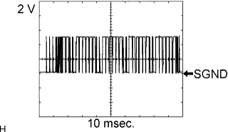
Using an oscilloscope, check waveform 1.
Item Content Terminal No. (Symbol) E86-22 (LRDD) - E86-10 (SGND) Tool Setting 2 V/DIV., 10 msec./DIV. Condition Engine switch on (IG) -
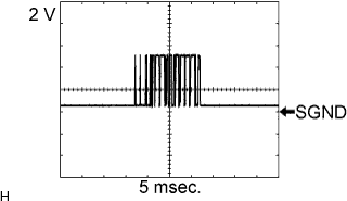
Using an oscilloscope, check waveform 2.
Item Content Terminal No. (Symbol) E86-23 (LRRD) - E86-10 (SGND) Tool Setting 2 V/DIV., 5 msec./DIV. Condition Engine switch on (IG)
-
-
CHECK MILLIMETER WAVE RADAR SENSOR

-
Disconnect the A44 millimeter wave radar sensor connector.
-
Measure the voltage according to the value(s) in the table below.
Terminal No. (Symbol) Wiring Color Terminal Description Condition Specified Condition A44-3 (LRDD) - A44-2 (SGND) B - R-W Millimeter wave radar sensor output signal Engine switch on (IG) Pulse generation
(See waveform 3)
A44-4 (LRRD) - A44-2 (SGND) W - R-W Millimeter wave radar sensor input signal Engine switch on (IG) Pulse generation
(See waveform 4)
A44-5 (IGB) - A44-2 (SGND) R-B - R-W Engine switch on signal Engine switch on (IG) 11 to 14 V Engine switch off Below 1 V If the result is not as specified, there may be a malfunction on the wire harness side.
-
Using an oscilloscope, check waveform 3.
Item Content Terminal No. (Symbol) A44-3 (LRDD) - A44-2 (SGND) Tool Setting 2 V/DIV., 10 msec./DIV. Condition Engine switch on (IG) -
Using an oscilloscope, check waveform 4.
Item Content Terminal No. (Symbol) A44-4 (LRRD) - A44-2 (SGND) Tool Setting 2 V/DIV., 5 msec./DIV. Condition Engine switch on (IG)
-