THERMOSTAT REMOVAL

Tech Tips
If the thermostat is not installed, cooling efficiency decreases. Do not remove the thermostat as this will cause the engine to overheat easily.
-
REMOVE V-BANK COVER SUB-ASSEMBLY
-
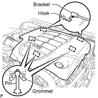
Raise the front of the V-bank cover to detach the 3 pins. Then remove the 2 V-bank cover hooks from the bracket, and remove the V-bank cover.
-
-
REMOVE ENGINE ROOM SIDE COVER LH
-
Remove the 7 clips and engine room side cover LH.
-
-
REMOVE ENGINE ROOM SIDE COVER RH
-
Remove the 7 clips and engine room side cover RH.
-
-
REMOVE UPPER RADIATOR SUPPORT SEAL
-
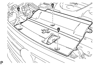
Remove the 3 clips and upper radiator support seal.
-
-
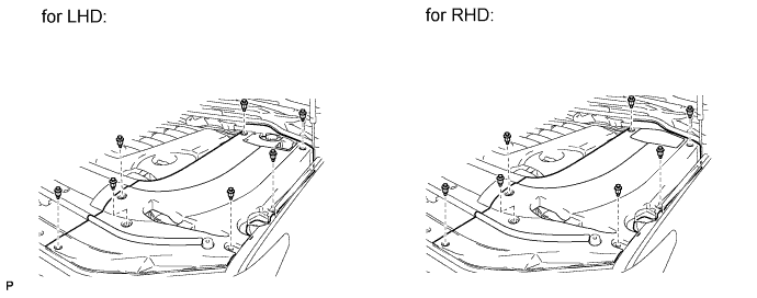
REMOVE FRONT FENDER SPLASH SHIELD SUB-ASSEMBLY LH
-
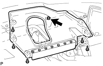
Remove the 3 bolts and 2 screws.
-
Turn the clip indicated by the arrow in the illustration to remove the front fender splash shield sub-assembly LH.
-
-
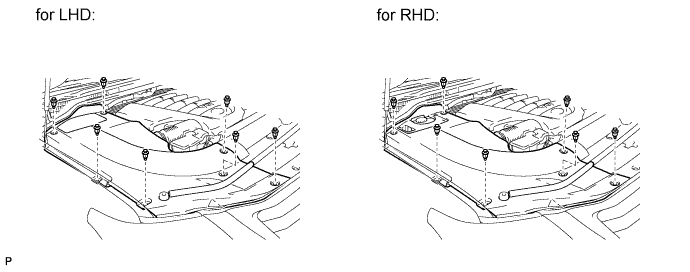
REMOVE FRONT FENDER SPLASH SHIELD SUB-ASSEMBLY RH
Tech Tips
Use the same procedure described for the LH side.
-
REMOVE NO. 1 ENGINE UNDER COVER SUB-ASSEMBLY
-
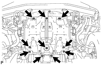
Remove the 10 bolts and No. 1 engine under cover.
-
-
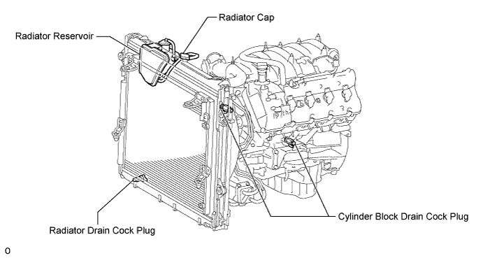
DRAIN ENGINE COOLANT
CAUTION:
Do not remove the radiator cap while the engine and radiator are still hot. Pressurized, hot engine coolant and steam may be released and cause serious burns.
-
Loosen the radiator drain cock plug.
Tech Tips
Collect the coolant in a container and dispose of it according to the regulations in your area.
-
Remove the radiator cap. Then drain the coolant from the radiator.
-
Loosen the 2 cylinder block drain cock plugs. Then drain the coolant from the engine.
-
Tighten the 2 cylinder block drain cock plugs.
- Torque:
- 13 N*m { 130 kgf*cm, 10 ft.*lbf }
-
Tighten the radiator drain cock plug by hand.
-
-
REMOVE AIR CLEANER HOSE ASSEMBLY
-
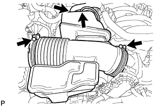
Disconnect the vacuum hose and No. 2 ventilation hose.
-
Loosen the 2 hose clamps.
-
Remove the air cleaner hose.
-
-
REMOVE AIR CLEANER ASSEMBLY
-
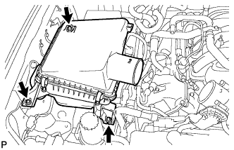
Remove the 3 bolts and air cleaner.
-
-
REMOVE NO. 1 RADIATOR HOSE
-
REMOVE NO. 2 RADIATOR HOSE
-
REMOVE FAN SHROUD
-
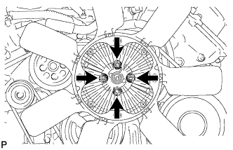
Loosen the 4 nuts holding the fluid coupling fan.
-
Remove the fan and generator V belt Click here.
-
Disconnect the reservoir hose from the upper radiator tank.
-
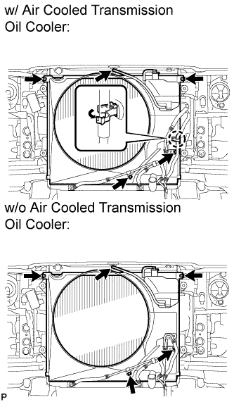
w/ Air Cooled Transmission Oil Cooler:
Detach the claw to open the flexible hose clamp.
-
Remove the 2 bolts and disconnect the oil cooler tube from the fan shroud.
-
Remove the 2 bolts holding the fan shroud.
-
Remove the 4 nuts of the fluid coupling fan, and then remove the shroud together with the coupling fan.
Note
Be careful not to damage the radiator core.
-
Remove the fan pulley.
-
-
REMOVE WATER INLET SUB-ASSEMBLY WITH THERMOSTAT
-
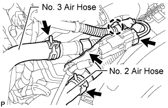
w/ Secondary Air Injection System:
-
Disconnect the No. 2 and No. 3 air hoses.
-
Disconnect the air pump connector.
-
Disconnect the air pump connector clamp holder.
-
Using a clip remover, detach the wire harness clamp.
-
-
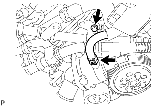
Disconnect the No. 5 water by-pass hose.
-
w/ Secondary Air Injection System:
Remove the air tube bracket bolt.
-
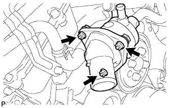
Remove the 3 nuts, water inlet with thermostat and gasket.
-