EXHAUST MANIFOLD REMOVAL

-
REMOVE ENGINE ROOM SIDE COVER LH
-
Remove the 7 clips and engine room side cover LH.
-
-
REMOVE ENGINE ROOM SIDE COVER RH
-
Remove the 7 clips and engine room side cover RH.
-
-
REMOVE UPPER RADIATOR SUPPORT SEAL
-
Remove the 3 clips and upper radiator support seal.
-
-
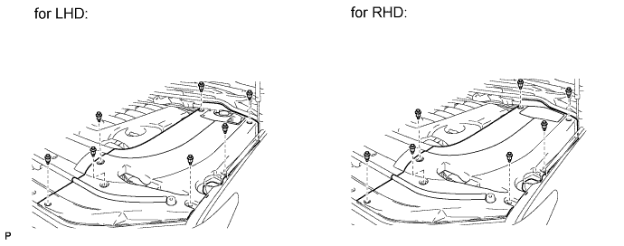
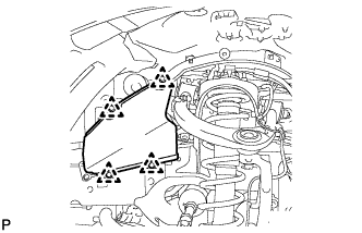
REMOVE FRONT FENDER SPLASH SHIELD SUB-ASSEMBLY LH
-
Remove the 3 bolts and 2 screws.
-
Turn the clip indicated by the arrow in the illustration to remove the front fender splash shield sub-assembly LH.
-
-
REMOVE FRONT FENDER SPLASH SHIELD SUB-ASSEMBLY RH
Tech Tips
Use the same procedure described for the LH side.
-
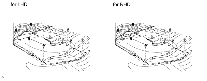
REMOVE NO. 1 ENGINE UNDER COVER SUB-ASSEMBLY
-
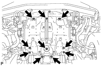
Remove the 10 bolts and No. 1 engine under cover.
-
-
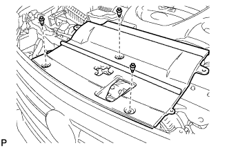
REMOVE NO. 2 ENGINE UNDER COVER
-
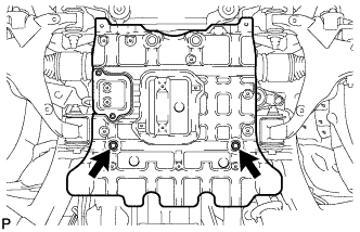
Remove the 2 bolts and No. 2 engine under cover.
-
-
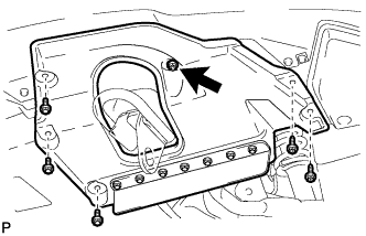
REMOVE FRONT FENDER APRON SEAL FRONT RH
-
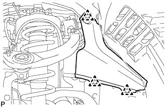
Using a clip remover, remove the 3 clips and fender apron seal.
-
-
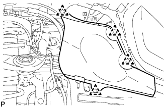
REMOVE FRONT FENDER APRON SEAL REAR RH
-
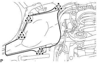
Using a clip remover, remove the 4 clips and fender apron seal.
-
-
REMOVE FRONT FENDER APRON SEAL FRONT LH
-
Using a clip remover, remove the 4 clips and fender apron seal.
-
-
REMOVE FRONT FENDER APRON SEAL REAR LH
-
Using a clip remover, remove the 4 clips and fender apron seal.
-
-
REMOVE ENGINE OIL LEVEL DIPSTICK GUIDE
-
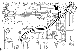
Remove the dipstick.
-
Remove the bolt and dipstick guide.
-
Remove the O-ring from the dipstick guide.
-
-
REMOVE TAILPIPE ASSEMBLY
-
Remove the bolt, clamp and gasket.
-
Remove the tailpipe from the 2 exhaust pipe supports.
-
Remove the bolt and clamp, and then disconnect the tailpipe from the center exhaust pipe.
-
-
REMOVE CENTER EXHAUST PIPE ASSEMBLY
-
Remove the 4 bolts.
-
Remove the center exhaust pipe from the 3 exhaust pipe supports.
-
Remove the 2 gaskets from the front exhaust pipe and front No. 2 exhaust pipe.
-
-
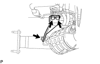
REMOVE FRONT NO. 2 EXHAUST PIPE ASSEMBLY
-
Disconnect the heated oxygen sensor connector.
-
Remove the bolt and disconnect the wire harness clamp bracket of the oxygen sensor from the transmission.
-
Remove the 2 nuts, front No. 2 exhaust pipe and gasket from the exhaust manifold LH.
-
-
REMOVE FRONT EXHAUST PIPE ASSEMBLY
-
Disconnect the heated oxygen sensor connector.
-
Remove the bolt and disconnect the wire harness clamp bracket of the oxygen sensor from the transmission.
-
Remove the 2 nuts, front exhaust pipe and gasket from the exhaust manifold RH.
-
-
REMOVE PROPELLER SHAFT HEAT INSULATOR
-
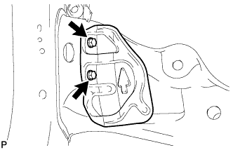
Remove the 2 bolts and heat insulator.
-
-
REMOVE NO. 2 MANIFOLD STAY
-
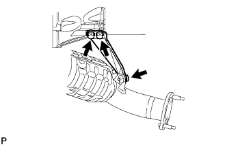
Remove the 3 bolts and manifold stay.
-
-
REMOVE NO. 2 EXHAUST MANIFOLD HEAT INSULATOR
-
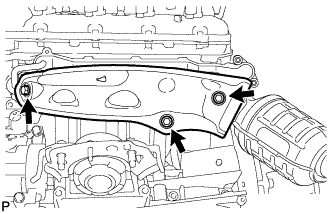
Remove the 3 bolts and heat insulator.
-
-
REMOVE EXHAUST MANIFOLD SUB-ASSEMBLY LH
-
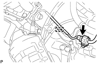
Disconnect the connector.
-
Using a clip remover, detach the wire harness clamp.
-
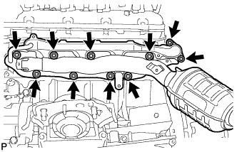
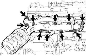
w/ Secondary Air Injection System:
Remove the 10 nuts, exhaust manifold and 2 gaskets.
-
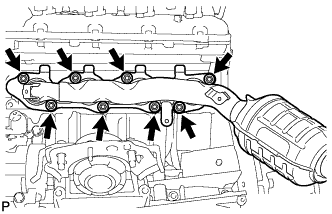
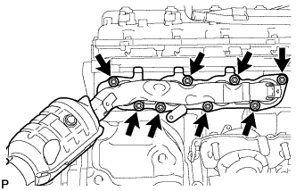
w/o Secondary Air Injection System:
Remove the 8 nuts, exhaust manifold and gasket.
-
-
REMOVE NO. 1 MANIFOLD STAY
-
Remove the 3 bolts and manifold stay.
-
-
REMOVE NO. 1 EXHAUST MANIFOLD HEAT INSULATOR
-
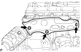
Remove the 3 bolts and heat insulator.
-
-
REMOVE EXHAUST MANIFOLD SUB-ASSEMBLY RH
-
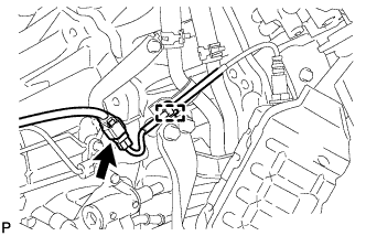
Disconnect the connector.
-
Using a clip remover, detach the wire harness clamp.
-
w/ Secondary Air Injection System:
Remove the 10 nuts, exhaust manifold and 2 gaskets.
-
w/o Secondary Air Injection System:
Remove the 8 nuts, exhaust manifold and gasket.
-
-
REMOVE AIR FUEL RATIO SENSOR (for Bank 1 Sensor 1)
-
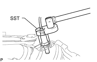
Using SST, remove the sensor.
- SST
- 09224-00010
-
-
REMOVE AIR FUEL RATIO SENSOR (for Bank 2 Sensor 1)
-
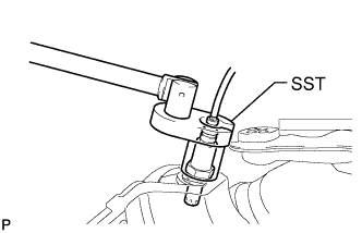
Using SST, remove the sensor.
- SST
- 09224-00010
-