VACUUM SWITCHING VALVE (for ACIS) ON-VEHICLE INSPECTION

-
REMOVE V-BANK COVER SUB-ASSEMBLY
-
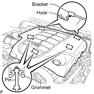
Raise the front of the V-bank cover to detach the 3 pins. Then remove the 2 V-bank cover hooks from the bracket, and remove the V-bank cover.
-
-
INSPECT VACUUM SWITCHING VALVE ASSEMBLY (for ACIS)
-
Disconnect the vacuum switching valve connector.
-
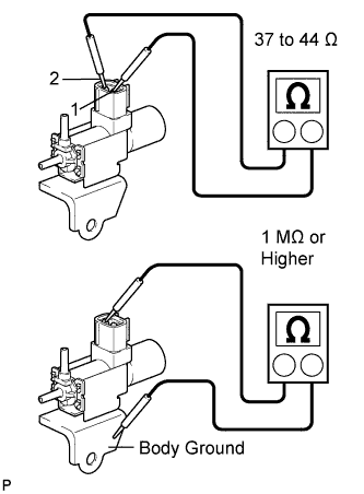
Measure the resistance according to the value(s) in the table below.
Standard Resistance Tester Connection Condition Specified Condition 1 - 2 20°C (68°F) 37 to 44 Ω 1 - Body ground Always 1 MΩ or higher 2 - Body ground If the result is not as specified, replace the vacuum switching valve assembly.
-
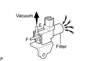
When applying vacuum to port E, check that air is sucked into the filter.
If the result is not as specified, replace the vacuum switching valve assembly.
-
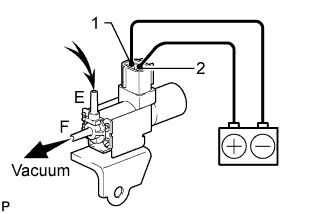
Apply battery voltage to the connector, and check the VSV operation.
OK Measurement Condition Specified Condition Battery positive (+) → Terminal 1
Battery negative (-) → Terminal 2
Air is sucked into port E when a vacuum is applied to port F If the result is not as specified, replace the vacuum switching valve assembly.
-
Connect the vacuum switching valve connector.
-
-
INSTALL V-BANK COVER SUB-ASSEMBLY
-
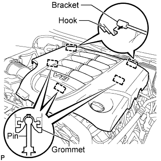
Attach the 2 V-bank cover hooks to the bracket. Then align the 3 V-bank cover grommets with the 3 pins, and press down on the V-bank cover to attach the pins.
-