OIL PUMP REMOVAL

-
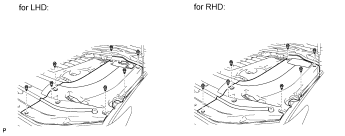
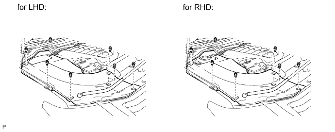
REMOVE ENGINE ROOM SIDE COVER LH
-
Remove the 7 clips and engine room side cover LH.
-
-
REMOVE ENGINE ROOM SIDE COVER RH
-
Remove the 7 clips and engine room side cover RH.
-
-
REMOVE UPPER RADIATOR SUPPORT SEAL
-
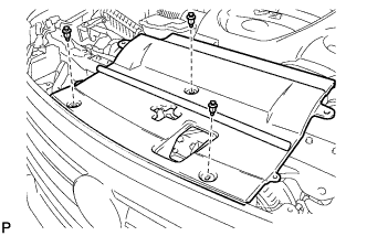
Remove the 3 clips and upper radiator support seal.
-
-
DISCHARGE FUEL SYSTEM PRESSURE
-
DISCONNECT CABLE FROM NEGATIVE BATTERY TERMINAL
Note
-
w/ Navigation System:
After the engine switch is turned off, the HDD navigation system requires approximately 6 minutes to record various types of memory and settings. As a result, after turning the engine switch off, wait 6 minutes or more before disconnecting the cable from the negative (-) battery terminal.
-
When disconnecting the cable, some systems need to be initialized after the cable is reconnected Click here.
-
-
REMOVE V-BANK COVER SUB-ASSEMBLY
-
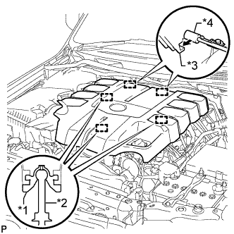
Text in Illustration *1 Grommet *2 Pin *3 Hook *4 Bracket Raise the front of the V-bank cover to detach the 3 pins. Then remove the 2 V-bank cover hooks from the bracket, and remove the V-bank cover.
-
-
REMOVE AIR CLEANER AND HOSE
-
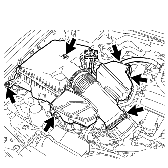
Disconnect the No. 2 PCV hose and No. 1 air hose.
-
Disconnect the mass air flow meter connector and detach the clamp.
-
Remove the 3 bolts and loosen the hose clamp, and then remove the air cleaner and hose.
-
-
REMOVE FRONT FENDER APRON TRIM PACKING A
-
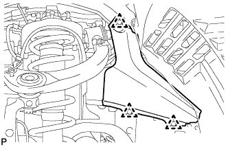
Remove the 3 clips and front fender apron trim packing A.
-
-
DRAIN ENGINE OIL
-
Remove the oil filler cap.
-
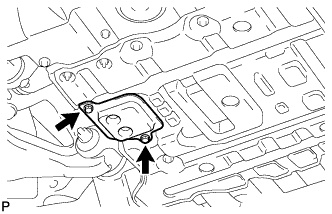
Remove the 2 bolts and No. 2 engine under cover seal.
-
Remove the oil pan drain plug and gasket, and drain the engine oil into a container.
-
Install a new gasket and the oil pan drain plug.
- Torque:
- 40 N*m { 408 kgf*cm, 30 ft.*lbf }
-
Install the No. 2 engine under cover seal with the 2 bolts.
- Torque:
- 10 N*m { 102 kgf*cm, 7 ft.*lbf }
-
-
REMOVE RADIATOR ASSEMBLY
-
REMOVE INTAKE MANIFOLD
-
DISCONNECT COOLER COMPRESSOR ASSEMBLY
-
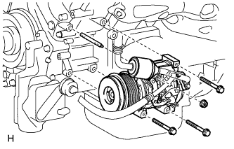
Remove the 3 bolts, nut and stud bolt and disconnect the cooler compressor.
Tech Tips
It is not necessary to completely remove the compressor. With the hoses connected to the compressor, hang the compressor on the vehicle body with a rope.
-
-
REMOVE AIR SWITCHING VALVE ASSEMBLY (for Bank 1)
-
REMOVE AIR SWITCHING VALVE ASSEMBLY (for Bank 2)
-
REMOVE AIR TUBE
-
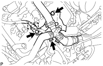
Detach the wire harness clamp.
-
Disconnect the No. 3 air injection system hose.
-
Remove the 2 bolts and air tube.
-
-
DISCONNECT ENGINE WIRE
-
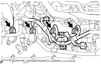
for Engine Room LH Side:
-
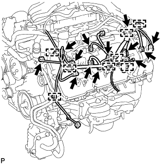
Disconnect the injector connector.
-
Disconnect the 2 camshaft timing oil control valve connectors.
-
Disconnect the 4 ignition coil connectors.
-
Disconnect the 2 VVT sensor connectors.
-
Disconnect the camshaft position sensor connector.
-
Disconnect the engine coolant temperature sensor connector.
-
Disconnect the noise filter connector.
-
Disconnect the 8 clamps.
-
Remove the bolt and ground wire.
-
-
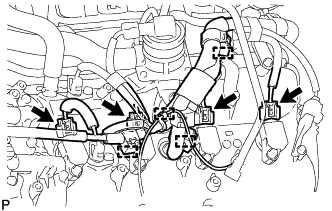
for Engine Room RH Side:
-
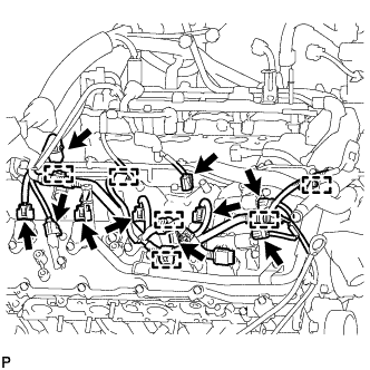
Disconnect the 2 camshaft timing oil control valve connectors.
-
Disconnect the 4 ignition coil connectors.
-
Disconnect the 2 VVT sensor connectors.
-
Disconnect the injector connector.
-
Disconnect the noise filter connector.
-
Disconnect the 6 clamps.
-
-
Remove the bolt and disconnect the clamp and engine wire.
-
-
REMOVE OIL FILTER ELEMENT
-
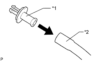
Text in Illustration *1 Pipe *2 Hose Connect a hose with an inside diameter of 15 mm (0.591 in.) to the pipe.
-
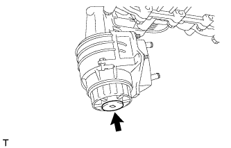
Remove the oil filter drain plug.
-
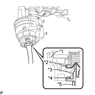
Text in Illustration *1 Cap *2 Valve *3 Pipe *4 O-Ring *5 Hose Install the pipe to the oil filter cap.
Note
If the O-ring is removed with the drain plug, install the O-ring together with the pipe.
Tech Tips
Use a container to catch the draining oil.
-
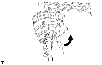
Check that oil is drained from the oil filter. Then disconnect the pipe and remove the O-ring as shown in the illustration.
-
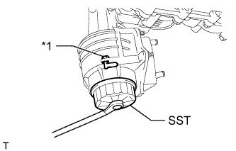
Text in Illustration *1 Oil Filter Bracket Clip Using SST, remove the oil filter cap.
- SST
- 09228-06501
Note
Do not remove the oil filter bracket clip.
-
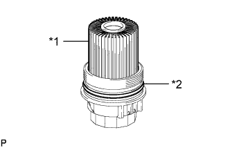
Text in Illustration *1 Oil Filter Element *2 O-Ring Remove the oil filter element and O-ring from the oil filter cap.
Note
Be sure to remove the cap O-ring by hand, without using any tools, to prevent damage to the cap O-ring groove.
-
-
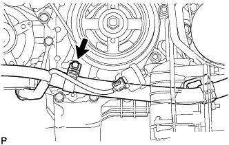
REMOVE OIL PRESSURE SENDER GAUGE ASSEMBLY
-
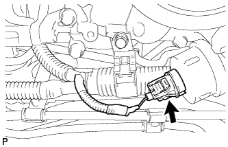
Disconnect the oil pressure sender gauge connector.
-
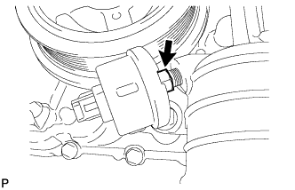
Remove the oil pressure sender gauge.
-
-
REMOVE NO. 1 OIL COOLER BRACKET
-
Remove the 2 nuts and bracket.
-
Disconnect the ground wire from the cylinder block.
-
-
REMOVE OIL FILTER BRACKET
-
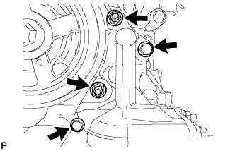
Remove the 2 bolts, 2 nuts and filter bracket.
-
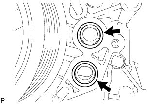
Remove the 2 O-rings.
-
-
REMOVE ENGINE OIL LEVEL DIPSTICK GUIDE
-
Remove the engine oil level dipstick.
-
Detach the engine wire clamp.
-
Remove the bolt and engine oil level dipstick guide.
-
Remove the O-ring from the engine oil level dipstick guide.
-
-
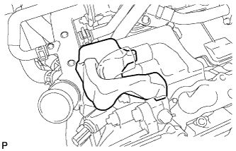
DISCONNECT VANE PUMP ASSEMBLY
-
Disconnect the connector.
-
Remove the 2 bolts and disconnect the vane pump.
-
-
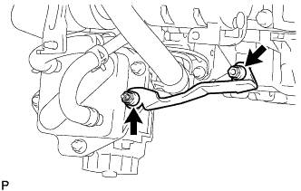
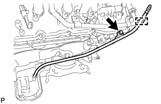
DISCONNECT OIL COOLER TUBE
-
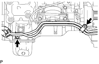
Remove the 2 bolts and disconnect the oil cooler tube.
-
-
REMOVE GENERATOR ASSEMBLY
-
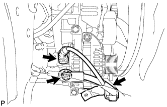
Disconnect the generator connector.
-
Open the terminal cap.
-
Remove the nut and disconnect the generator wire.
-
Remove the bolt and disconnect the wire harness bracket from the generator.
-
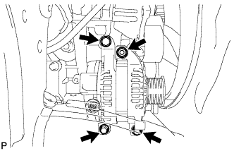
Remove the 3 bolts, nut and generator.
-
Remove the stud bolt.
-
-
REMOVE NO. 4 ENGINE COVER
-
REMOVE NO. 3 ENGINE COVER
-
REMOVE FUEL TUBE SUB-ASSEMBLY
-
Remove the 2 bolts and fuel tube Click here.
-
-
REMOVE FUEL HOSE
-
Remove the fuel pipe clamp.
-

Disconnect the 2 clamps and remove the fuel hose Click here.
-
-
REMOVE NO. 4 AIR TUBE
-
Remove the bolt and bracket.
-
Remove the bolt, 2 nuts, 2 stud bolts, No. 4 air tube and gasket.
-
-
REMOVE NO. 3 AIR TUBE
-
Remove the bolt, 2 nuts, 2 stud bolts, No. 3 air tube and gasket.
-
-
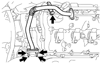
REMOVE NO. 1 WATER BY-PASS PIPE
-
Disconnect the heater water hose.
-
Remove the 2 bolts and disconnect the No. 1 water by-pass pipe.
-
-
DISCONNECT WATER BY-PASS HOSE
-
Disconnect the water by-pass hose.
-
-
REMOVE NO. 1 WATER BY-PASS HOSE
-
Remove the No. 1 water by-pass hose.
-
-
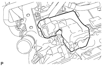
REMOVE NO. 2 WATER BY-PASS PIPE SUB-ASSEMBLY
-
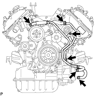
Remove the 2 bolts.
-
Disconnect the 4 hoses and remove the No. 2 water by-pass pipe.
-
-
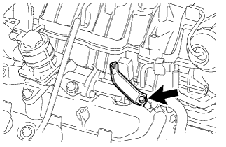
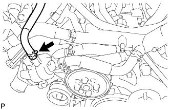
DISCONNECT NO. 5 WATER BY-PASS HOSE
-
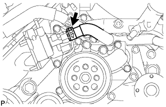
Disconnect the No. 5 water by-pass hose.
-
-
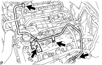
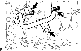
REMOVE WATER BY-PASS PIPE SUB-ASSEMBLY
-
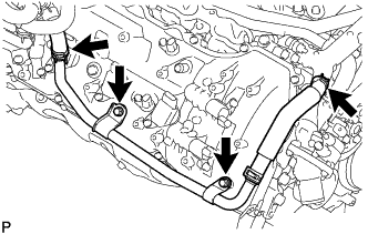
Disconnect the No. 2 water by-pass hose from the front water by-pass joint.
-
Disconnect the heater hose.
-
Remove the 2 bolts and water by-pass pipe sub-assembly.
-
-
REMOVE WATER INLET HOUSING
-

Remove the 3 bolts and water inlet housing.
-
Remove the gasket from the engine water pump.
-
-
REMOVE FRONT WATER BY-PASS JOINT
-
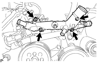
Remove the 4 nuts, water by-pass joint and 2 gaskets.
-
-
REMOVE WATER PUMP PULLEY
-
Temporarily install the water pump pulley with the 4 bolts.
-
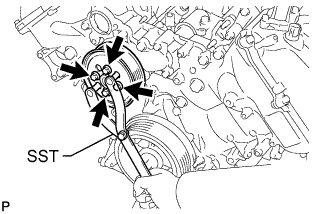
Using SST, hold the water pump pulley and tighten the 4 bolts.
- SST
- 09960-10010 ( 09962-01000, 09963-01000 )
- Torque:
- 21 N*m { 214 kgf*cm, 15 ft.*lbf }
-
-
REMOVE NO. 1 IDLER PULLEY SUB-ASSEMBLY
-
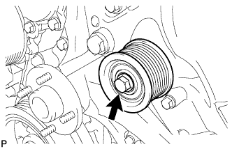
Remove the bolt and No. 1 idler pulley.
-
-
REMOVE FAN BRACKET ASSEMBLY
-
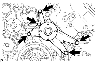
Remove the 5 bolts and fan bracket.
-
-
REMOVE V-RIBBED BELT TENSIONER ASSEMBLY
-
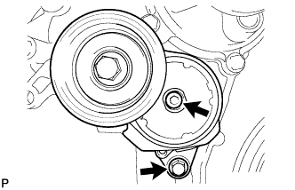
Remove the bolt, 6 mm hexagon bolt and belt tensioner.
-
-
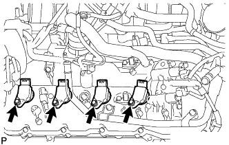
REMOVE IGNITION COIL ASSEMBLY
-
for Bank 1:
-
Detach the 4 clamps and disconnect the engine wire.
-
Disconnect the 4 ignition coil connectors.
-
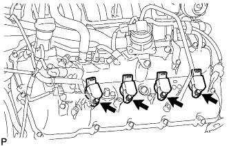
Remove the 4 bolts and 4 ignition coils.
-
-
for Bank 2:
-
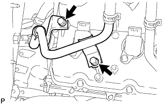
Remove the 2 bolts and disconnect the water by-pass pipe.
-
Detach the 3 clamps and disconnect the engine wire.
-
Disconnect the 4 ignition coil connectors.
-
Remove the 4 bolts and 4 ignition coils.
-
-
-
REMOVE CYLINDER HEAD COVER SUB-ASSEMBLY LH
-

Remove the 14 bolts, seal washer, cylinder head cover sub-assembly LH and cylinder head cover gasket LH.
Tech Tips
Make sure the removed parts are returned to the same places they were removed from.
-
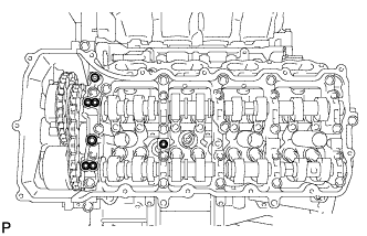
Remove the 5 gaskets from the camshaft bearing caps (No. 2, No. 3).
Text in Illustration 
Gasket
-
-
REMOVE CYLINDER HEAD COVER SUB-ASSEMBLY RH
-
Remove the 14 bolts, seal washer, cylinder head cover sub-assembly RH and cylinder head cover gasket RH.
Tech Tips
Make sure the removed parts are returned to the same places they were removed from.
-
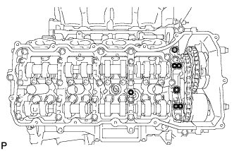
Remove the 5 gaskets from the camshaft bearing caps (No. 1, No. 3).
Text in Illustration Gasket
-
-
REMOVE CRANKSHAFT PULLEY
-
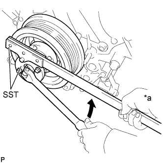
Text in Illustration *a Hold 
Turn Using SST, remove the crankshaft pulley set bolt.
- SST
- 09213-70011
- 09330-00021
-
Temporarily install the pulley set bolt to the crankshaft until 2 or 3 threads are engaged.
-
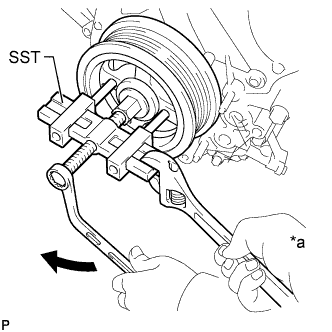
Text in Illustration *a Hold Turn Using the pulley set bolt and SST, remove the crankshaft pulley.
- SST
- 09950-50013 ( 09951-05010, 09952-05010, 09953-05010, 09954-05011 )
-
-
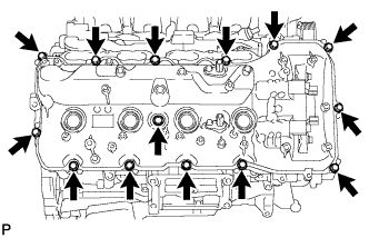
REMOVE TIMING CHAIN COVER SUB-ASSEMBLY
-
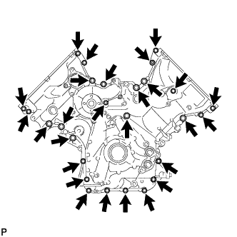
Remove the 26 bolts and nut shown in the illustration.
-
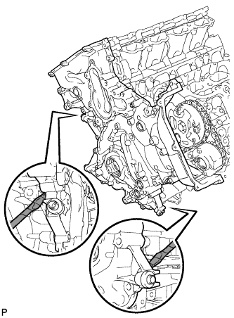
Remove the timing chain cover by prying between it and the cylinder head and cylinder block with a screwdriver as shown in the illustration.
Text in Illustration 
Protective Tape Note
Be careful not to damage the cylinder head, camshaft housing and cylinder block contact surfaces of the chain cover.
Tech Tips
Tape the screwdriver tip before use.
-
Remove the gasket from the cylinder block.
-
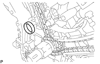
Remove the O-ring from the oil pan.
-
-
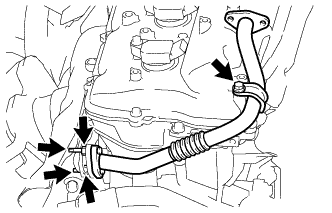
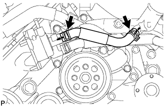
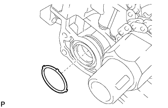
REMOVE WATER INLET PIPE
-
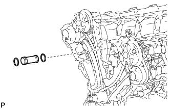
Remove the water inlet pipe.
-
Remove the 2 O-rings from the water inlet pipe.
-
-
REMOVE FRONT CRANKSHAFT OIL SEAL
-
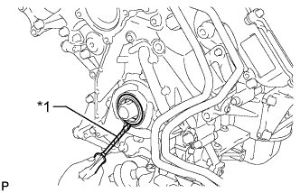
Text in Illustration *1 Protective Tape Using a screwdriver, pry out the front crankshaft oil seal.
Note
Do not damage the surface of the front crankshaft oil seal press fit hole or crankshaft.
Tech Tips
Tape the screwdriver tip before use.
-