AIR PUMP (w/ Secondary Air Injection System) INSTALLATION

-
INSTALL AIR PUMP ASSEMBLY
-
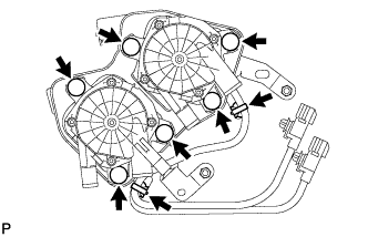
Connect the 6 air pump insulators to the 2 air pump assemblies and install the 2 air pump assemblies to the bracket.
-
Attach the 2 wire harness clamps to the bracket.
-
-
CONNECT NO. 1 AIR INJECTION SYSTEM HOSE
-
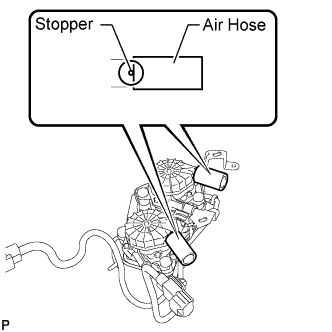
Connect the 2 hoses to the air pump.
Tech Tips
Connect the hoses so that the hose ends are aligned with the stoppers.
-
-
INSTALL AIR PUMP INLET
-
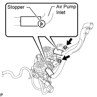
Connect the air pump inlet to the 2 No. 1 air injection system hoses.
Tech Tips
Insert the inlet until the inlet stoppers are aligned with the hose ends.
-
Install the 2 bolts.
- Torque:
- 8.0 N*m { 82 kgf*cm, 71 in.*lbf }
-
-
INSTALL AIR PUMP ASSEMBLY WITH BRACKET
-
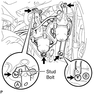
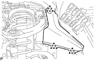
Install the air pump assembly with bracket to the vehicle.
-
Insert the bracket tab into the slot and insert the stud bolt into the bracket hole as shown in illustration A. Then slide the bracket.
-
Insert the bracket tab into the slot shown in illustration B.
-
Install the 2 bolts and 2 nuts.
- Torque:
- 18 N*m { 184 kgf*cm, 13 ft.*lbf }
-
-
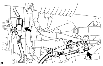
Connect the 2 air pump connectors and attach the 3 wire harness claws.
-
-
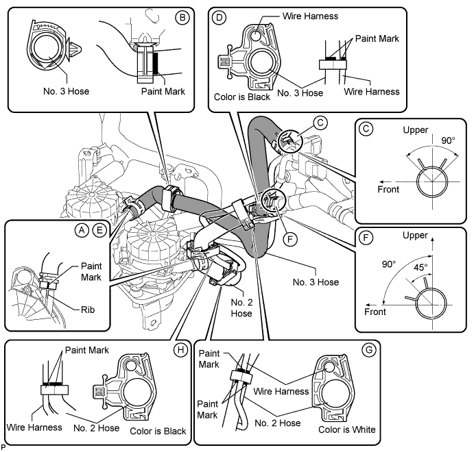
INSTALL NO. 3 AIR INJECTION SYSTEM HOSE
-
Connect the No. 3 hose so that its paint mark aligns with the rib of the air pump as shown in the illustration below labeled A.
Tech Tips
Make sure the direction of the hose clamp is as shown in the illustration.
-
Connect the clamp to the No. 3 hose shown in the illustration below labeled B. Then insert the clip of the clamp into the bracket.
Tech Tips
Align the paint mark of the No. 3 hose with the edge of the clamp.
-
Connect the No. 3 hose to the air tube shown in the illustration below labeled C.
Tech Tips
-
Make sure the paint mark of the No. 3 hose is facing upward.
-
Make sure the direction of the hose clamp is as shown in the illustration.
-
-
Connect the clamp to the No. 3 hose and wire harness shown in the illustration below labeled D. Then insert the clip of the clamp into the body hole.
Tech Tips
Align the paint mark of the No. 3 hose and paint mark of the wire harness with the edge of the clamp.
-
-
INSTALL NO. 2 AIR INJECTION SYSTEM HOSE
-
Connect the No. 2 hose so that its paint mark aligns with the rib of the air pump as shown in the illustration below labeled E.
Tech Tips
Make sure the direction of the hose clamp is as shown in the illustration.
-
Connect the No. 2 hose to the air tube shown in the illustration below labeled F.
Tech Tips
-
Make sure the paint mark of the No. 2 hose is facing upward.
-
Make sure the direction of the hose clamp is as shown in the illustration.
-
-
Connect the 2 white colored clamps to the No. 2 hose and wire harness shown in the illustration below labeled G.
Tech Tips
-
Make sure the paint mark of the No. 2 hose is facing upward.
-
Make sure the position of the hose clamp is as shown in the illustration.
-
-
Connect the black colored clamp to the No. 2 hose and wire harness shown in the illustration below labeled H. Then insert the clip of the clamp into the body hole.
Tech Tips
Align the paint mark of the No. 2 hose and paint mark of the wire harness with the edge of the clamp.
-
-
INSTALL AIR CLEANER ASSEMBLY
-
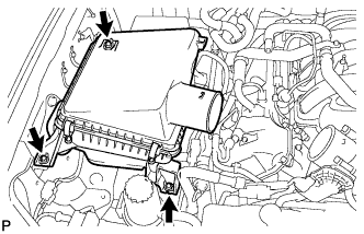
Install the air cleaner with the 3 bolts.
- Torque:
- 5.0 N*m { 51 kgf*cm, 44 in.*lbf }
-
-
INSTALL AIR CLEANER HOSE ASSEMBLY
-
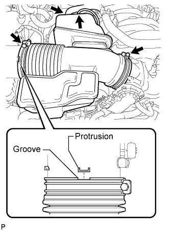
Install the air cleaner hose so that the protrusion of the air cleaner cap aligns with the groove of the hose as shown in the illustration.
-
Tighten the 2 clamps.
- Torque:
- 5.0 N*m { 51 kgf*cm, 44 in.*lbf }
-
Connect the vacuum hose.
-
Connect the No. 2 ventilation hose.
-
-
INSTALL FRONT FENDER APRON SEAL FRONT RH
-
Install the fender apron seal with the 3 clips.
-
-
INSTALL FRONT FENDER LINER RH
-
Install the fender liner with the 5 clips.
-
Using a T30 "TORX" socket, install the 3 screws.
-
Connect the liner to the front bumper cover with the screw.
-
-
INSTALL FRONT FENDER SPLASH SHIELD SUB-ASSEMBLY RH
-
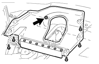
Push in the clip indicated by the arrow in the illustration to install the fender splash shield.
-
Install the 3 bolts and 2 screws.
-
-
CONNECT CABLE TO NEGATIVE BATTERY TERMINAL
Note
When disconnecting the cable, some systems need to be initialized after the cable from the cable is reconnected Click here.
-
INSTALL V-BANK COVER SUB-ASSEMBLY
-
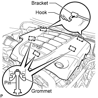
Attach the 2 V-bank cover hooks to the bracket. Then align the 3 V-bank cover grommets with the 3 pins, and press down on the V-bank cover to attach the pins.
-
-
INSTALL UPPER RADIATOR SUPPORT SEAL
-
Install the upper radiator support seal with the 3 clips.
-
-
INSTALL ENGINE ROOM SIDE COVER LH
-
Install the engine room side cover LH with the 7 clips.
-
-
INSTALL ENGINE ROOM SIDE COVER RH
-
Install the engine room side cover RH with the 7 clips.
-