EMISSION CONTROL SYSTEM (w/ Secondary Air Injection System) ON-VEHICLE INSPECTION

-
CHECK PURGE VSV
-
Connect the intelligent tester to the DLC3.
-
Remove the V-bank cover Click here.
-
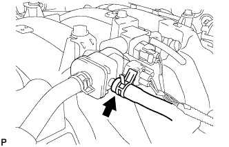
Disconnect the hose (connected to the canister) from the purge VSV.
-
Start the engine and turn the tester main switch on.
-
Enter the following menus: Powertrain / Engine and ECT / Active Test / Activate the VSV for Evap Control.
OK Tester Operation Specified Condition Activate the VSV for Evap Control: OFF Purge VSV has no suction Activate the VSV for Evap Control: ON Purge VSV has suction -
Connect the hose (connected to the canister) to the purge VSV.
-
Install the V-bank cover Click here.
-
-
INSPECT FUEL CUT-OFF RPM
-
Start and warm up the engine.
-
Open the throttle valve and keep the engine speed at 3000 rpm.
-
Use a sound scope to check for injector operating noise.
-
Check that when the accelerator pedal is released, the injector operation noise stops momentarily and then resumes.
If the result is as not specified, check the injector, wiring and ECM.
-
-
VISUALLY INSPECT HOSES, CONNECTIONS AND GASKETS
-
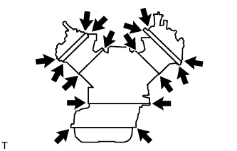
Check that there are no cracks, leaks or damage.
Tech Tips
Separation of the engine oil dipstick, oil filler cap, ventilation hose, etc. may cause an engine failure or engine malfunctions. Disconnection, looseness or cracks in the parts of the air induction system between the throttle body and cylinder head will allow air suction and cause an engine failure or engine malfunctions.
Note
-
Detachment or other problems with the engine oil dipstick, filler cap, ventilation hose and other components may cause the engine to run improperly.
-
Disconnection, looseness or cracks in the parts of the air induction system between the throttle body and cylinder head will allow air suction and cause an engine failure or engine malfunctions.
If the result is not as specified, replace parts as necessary.
-
-
-
CHECK HOSES AND CONNECTORS
-
Visually check for loose connections, sharp bends or damage.
-
-
CHECK FUEL TANK ASSEMBLY
-
Visually check for deformation, cracks or fuel leakage.
-
-
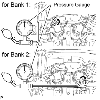
INSPECT PRESSURE SENSOR
-
Connect a pressure gauge to the air pressure sensor as shown in the illustration.
-
Connect the intelligent tester to the DLC3.
-
Turn the engine switch on (IG) and turn the tester main switch on.
-
Enter the following menus: Powertrain / Engine and ECT / Data List / All Data / Air pump pressure (absolute).
-
Check that the pressure displayed on the intelligent tester fluctuates when applying pressure to the pressure sensor with the pressure gauge.
Note
Do not let foreign matter enter the sensor when applying pressure.
OK Pressure fluctuates in response to pressure applied with pressure gauge. -
Check the power source voltage.
-
Disconnect the connector.
-
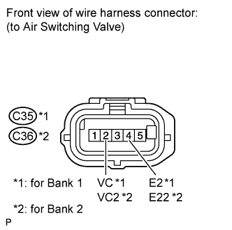
Measure the voltage according to the value(s) in the table below.
Standard Voltage Tester Connection Switch Condition Specified Condition C35-2 (VC) - C35-4 (E2) Engine switch on (IG) 4.75 to 5.25 V C36-2 (VC2) - C36-4 (E22) If the result is not as specified, check the wiring and ECM Click here.
-
-