EXHAUST MANIFOLD INSTALLATION

-
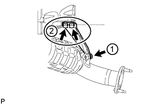
INSTALL AIR FUEL RATIO SENSOR (for Bank 1 Sensor 1)
-
Temporarily install the air fuel ratio sensor to the exhaust manifold LH by hand.
-
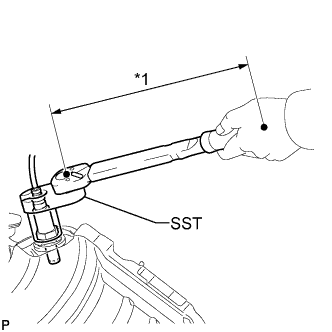
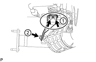
Text in Illustration *1 Fulcrum Length Using SST, tighten the air fuel ratio sensor.
- SST
- 09224-00010
- Torque:
- without SST
- 44 N*m { 449 kgf*cm, 32 ft.*lbf }
- with SST
- 40 N*m { 408 kgf*cm, 30 ft.*lbf }
Tech Tips
-
Use a torque wrench with a fulcrum length of 300 mm (11.8 in.). When using a torque wrench with a fulcrum length that is not 300 mm (11.8 in.), calculate the torque specification for the torque wrench and SST based on the "without SST" torque specification Click here.
-
Make sure SST and the wrench are connected in a straight line.
-
-
INSTALL AIR FUEL RATIO SENSOR (for Bank 2 Sensor 1)
-
Temporarily install the air fuel ratio sensor to the exhaust manifold RH by hand.
-
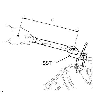
Text in Illustration *1 Fulcrum Length Using SST, tighten the air fuel ratio sensor.
- SST
- 09224-00010
- Torque:
- without SST
- 44 N*m { 449 kgf*cm, 32 ft.*lbf }
- with SST
- 40 N*m { 408 kgf*cm, 30 ft.*lbf }
Tech Tips
-
Use a torque wrench with a fulcrum length of 300 mm (11.8 in.). When using a torque wrench with a fulcrum length that is not 300 mm (11.8 in.), calculate the torque specification for the torque wrench and SST based on the "without SST" torque specification Click here.
-
Make sure SST and the wrench are connected in a straight line.
-
-
INSTALL EXHAUST MANIFOLD ASSEMBLY RH
-
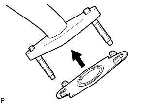
Install a new gasket to the No. 3 air tube.
Tech Tips
Install the gasket with the claws of the gasket facing the tube.
-
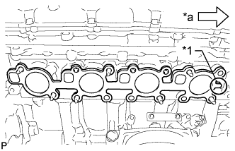
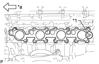
Text in Illustration *1 Tab *a Front Install a new gasket to the cylinder head.
Tech Tips
Install the gasket with the gasket tab facing toward the front of the engine.
-
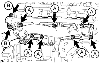
Install the exhaust manifold to the cylinder head with the 7 new nuts labeled A.
- Torque:
- 21 N*m { 214 kgf*cm, 15 ft.*lbf }
-
Install the exhaust manifold to the No. 3 air tube with the 2 nuts labeled B.
- Torque:
- 10 N*m { 102 kgf*cm, 7 ft.*lbf }
-
Connect the air fuel ratio sensor connector and attach the wire harness clamp.
-
-
INSTALL NO. 1 EXHAUST MANIFOLD HEAT INSULATOR
-
Install the heat insulator with 3 new bolts.
- Torque:
- 10 N*m { 102 kgf*cm, 7 ft.*lbf }
-
-
INSTALL ENGINE OIL LEVEL DIPSTICK GUIDE
-
Apply engine oil to a new O-ring, and then install the O-ring to the engine oil level dipstick guide.
-
Install the engine oil level dipstick guide with the bolt.
- Torque:
- 10 N*m { 102 kgf*cm, 7 ft.*lbf }
-
Attach the engine wire clamp.
-
Install the engine oil level dipstick.
-
-
INSTALL MANIFOLD STAY
-
Temporarily install the manifold stay with the 3 bolts.
-
Tighten the 3 bolts in the sequence shown in the illustration.
- Torque:
- 40 N*m { 408 kgf*cm, 30 ft.*lbf }
-
-
INSTALL EXHAUST MANIFOLD ASSEMBLY LH
-
Install a new gasket to the No. 4 air tube.
Tech Tips
Install the gasket with the claws of the gasket facing the tube.
-
Text in Illustration *1 Tab *a Front Install a new gasket to the cylinder head.
Tech Tips
Install the gasket with the gasket tab facing toward the rear of the engine.
-
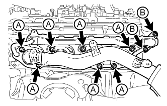
Install the exhaust manifold to the cylinder head with the 7 new nuts labeled A.
- Torque:
- 21 N*m { 214 kgf*cm, 15 ft.*lbf }
-
Install the exhaust manifold to the No. 4 air tube with the 2 nuts labeled B.
- Torque:
- 10 N*m { 102 kgf*cm, 7 ft.*lbf }
-
Connect the air fuel ratio sensor connector and attach the wire harness clamp.
-
-
INSTALL NO. 2 EXHAUST MANIFOLD HEAT INSULATOR
-
Install the heat insulator with 3 new bolts.
- Torque:
- 10 N*m { 102 kgf*cm, 7 ft.*lbf }
-
-
INSTALL NO. 2 MANIFOLD STAY
-
Temporarily install the manifold stay with the 3 bolts.
-
Tighten the 3 bolts in the sequence shown in the illustration.
- Torque:
- 40 N*m { 408 kgf*cm, 30 ft.*lbf }
-
-
INSTALL PROPELLER SHAFT HEAT INSULATOR
-
Install the propeller shaft heat insulator with the 2 bolts.
- Torque:
- 16 N*m { 160 kgf*cm, 12 ft.*lbf }
-
-
INSTALL FRONT PROPELLER SHAFT ASSEMBLY
-
INSTALL FRONT EXHAUST PIPE ASSEMBLY
-
INSPECT FOR EXHAUST GAS LEAK
If gas is leaking, tighten the areas necessary to stop the leak. Replace damaged parts as necessary.
-
INSTALL FRONT FENDER APRON TRIM PACKING C
-
Install the front fender apron trim packing C with the 4 clips.
-
-
INSTALL FRONT FENDER APRON TRIM PACKING A
-
Install the front fender apron trim packing A with the 3 clips.
-
-
INSTALL FRONT FENDER APRON TRIM PACKING D
-
Install the front fender apron trim packing D with the 4 clips.
-
-
INSTALL FRONT FENDER APRON TRIM PACKING B
-
Install the front fender apron trim packing B with the 4 clips.
-
-
INSTALL NO. 2 ENGINE UNDER COVER
-
Install the No. 2 engine under cover with the 2 bolts.
- Torque:
- 29 N*m { 296 kgf*cm, 21 ft.*lbf }
-
-
INSTALL NO. 1 ENGINE UNDER COVER SUB-ASSEMBLY
-
Install the No. 1 engine under cover sub-assembly with the 10 bolts.
- Torque:
- 29 N*m { 296 kgf*cm, 21 ft.*lbf }
-
-
INSTALL FRONT FENDER SPLASH SHIELD SUB-ASSEMBLY LH
-
Push in the clip to install the front fender splash shield sub-assembly LH.
-
Install the 3 bolts and 2 screws.
-
-
INSTALL FRONT FENDER SPLASH SHIELD SUB-ASSEMBLY RH
Tech Tips
Use the same procedure described for the LH side.
-
INSTALL AIR CLEANER AND HOSE
-
Install the air cleaner and hose with the 3 bolts, and then tighten the hose clamp.
- Torque:
- for bolt
- 5.0 N*m { 51 kgf*cm, 44 in.*lbf }
- for hose clamp
- 2.5 N*m { 25 kgf*cm, 22 in.*lbf }
-
Attach the clamp and connect the mass air flow meter connector.
-
Connect the No. 2 PCV hose and No. 1 air hose.
-
-
INSTALL V-BANK COVER SUB-ASSEMBLY
-
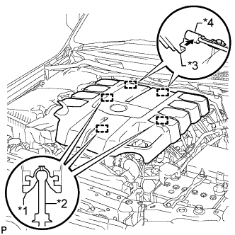
Text in Illustration *1 Grommet *2 Pin *3 Hook *4 Bracket Attach the 2 V-bank cover hooks to the bracket. Then align the 3 V-bank cover grommets with the 3 pins, and press down on the V-bank cover to attach the pins.
-
-
INSTALL UPPER RADIATOR SUPPORT SEAL
-
Install the upper radiator support seal with the 3 clips.
-
-
INSTALL ENGINE ROOM SIDE COVER RH
-
Install the engine room side cover RH with the 7 clips.
-
-
INSTALL ENGINE ROOM SIDE COVER LH
-
Install the engine room side cover LH with the 7 clips.
-