INTAKE MANIFOLD INSTALLATION

-
INSTALL THROTTLE BODY WITH MOTOR ASSEMBLY
-
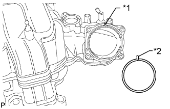
Text in Illustration *1 Groove *2 Protrusion Align the protrusion of a new gasket with the groove of the intake manifold and install the gasket.
-
Install the throttle body with motor assembly with the 4 bolts.
- Torque:
- 10 N*m { 102 kgf*cm, 7 ft.*lbf }
-
-
INSTALL MANIFOLD ABSOLUTE PRESSURE SENSOR
-
Install the manifold absolute pressure sensor with the bolt.
- Torque:
- 9.0 N*m { 92 kgf*cm, 80 in.*lbf }
-
Connect the manifold absolute pressure sensor connector.
-
-
INSTALL PURGE VSV
-
Connect the purge line hose to the intake manifold.
-
Install the purge VSV to the intake manifold with the bolt.
- Torque:
- 21 N*m { 214 kgf*cm, 15 ft.*lbf }
-
-
INSTALL VACUUM SWITCHING VALVE ASSEMBLY (for ACIS)
-
Install the vacuum switching valve to the intake manifold with the bolt.
- Torque:
- 9.0 N*m { 92 kgf*cm, 80 in.*lbf }
-
Connect the 2 vacuum hoses to the vacuum switching valve and attach the 3 clamps.
-
-
INSTALL STUD BOLT
Note
If a stud bolt is deformed or its threads are damaged, replace it.
-
Using an E5 "TORX" socket wrench, install the 2 stud bolts to the intake manifold.
- Torque:
- 5.0 N*m { 51 kgf*cm, 44 in.*lbf }
-
-
INSTALL INTAKE FLANGE
-
Install the intake flange with the 2 nuts.
- Torque:
- 10 N*m { 102 kgf*cm, 7 ft.*lbf }
-
-
INSTALL V-BANK COVER PIN
-
Install the V-bank cover pin to the intake manifold.
- Torque:
- 10 N*m { 102 kgf*cm, 7 ft.*lbf }
-
-
INSTALL V-BANK COVER BRACKET
-
Install the V-bank cover bracket with the 2 bolts.
- Torque:
- 10 N*m { 102 kgf*cm, 7 ft.*lbf }
-
-
INSTALL BRACKET
-
Install the 2 brackets with the 2 bolts.
- Torque:
- 8.0 N*m { 82 kgf*cm, 71 in.*lbf }
-
-
INSTALL FUEL TUBE SUB-ASSEMBLY
-
Install the fuel tube to the intake manifold with the bolt.
- Torque:
- 10 N*m { 102 kgf*cm, 7 ft.*lbf }
-
-
INSTALL INTAKE MANIFOLD
-
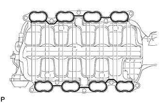
Place 2 new gaskets on the intake manifold.
-
Place the intake manifold on the cylinder head.
-
Install and uniformly tighten the 8 bolts and 2 nuts in several steps.
- Torque:
- 21 N*m { 214 kgf*cm, 15 ft.*lbf }
-
Connect the fuel tube to the No. 2 fuel delivery pipe Click here.
-
Connect the fuel tube to the fuel delivery pipe Click here.
-
Attach the 3 wire harness clamps to the 3 wire harness brackets.
-
Install the bolt.
- Torque:
- 8.0 N*m { 82 kgf*cm, 71 in.*lbf }
-
Connect the purge VSV connector.
-
Connect the purge line hose to the purge VSV.
-
Connect the vacuum switching valve connector (for ACIS).
-
Connect the PCV valve hose.
-
Connect the No. 4 water by-pass hose.
-
Connect the throttle position sensor and throttle control motor connector.
-
-
INSTALL AIR TUBE SUB-ASSEMBLY
-
Install the air tube.
-
Install the bolt.
- Torque:
- 10 N*m { 102 kgf*cm, 7 ft.*lbf }
-
Install the bracket with the 2 bolts.
- Torque:
- 10 N*m { 102 kgf*cm, 7 ft.*lbf }
-
Attach the clamp and connect the manifold absolute pressure sensor connector.
-
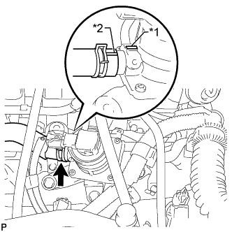
Text in Illustration *1 Projection *2 Paint Mark Align the paint mark with the projection and connect the No. 2 air injection system hose.
Tech Tips
Make sure the direction of the hose clamp is as shown in the illustration.
-
-
INSTALL PCV HOSE ASSEMBLY
-
Install the PCV hose with the bolt.
- Torque:
- 10 N*m { 102 kgf*cm, 7 ft.*lbf }
-
Connect the PCV hose to the PCV pipe of the cylinder head cover LH and RH.
-
-
INSTALL EGR VALVE BRACKET
-
Install the EGR valve bracket with the 3 bolts.
- Torque:
- 21 N*m { 214 kgf*cm, 15 ft.*lbf }
-
Attach the 2 wire harness clamps and PCV hose clamp.
-
-
INSTALL NO. 5 WATER BY-PASS PIPE
-
Install the No. 5 water by-pass pipe with the 2 bolts and connect the 2 water by-pass hoses.
- Torque:
- 21 N*m { 214 kgf*cm, 15 ft.*lbf }
-
-
ADD ENGINE COOLANT
-
Add engine coolant.
Standard capacity 16.5 liters (17.4 US qts, 14.5 Imp. qts) Note
Do not substitute plain water for engine coolant.
Tech Tips
-
TOYOTA vehicles are filled with TOYOTA SLLC at the factory. In order to avoid damage to the engine cooling system and other technical problems, only use TOYOTA SLLC or similar high quality ethylene glycol based non-silicate, non-amine, non-nitrite, non-borate coolant with long-life hybrid organic acid technology (coolant with long-life hybrid organic acid technology consists of a combination of low phosphates and organic acids).
-
Press the No. 1 and No. 2 radiator hoses several times by hand, and then check the coolant level. If the coolant level is low, add coolant.
-
-
Slowly pour coolant into the radiator reservoir until it reaches the F line.
-
Install the reservoir cap.
-
Install the radiator cap.*1
-
Start the engine and stop it immediately.*2
-
Allow approximately 10 seconds to pass. Then remove the radiator cap and check the coolant level. If the coolant level has decreased, add coolant.*3
-
Repeat steps *1, *2 and *3 until the coolant level does not decrease.
Tech Tips
Be sure to perform this step while the engine is cold, as air in the No. 1 radiator hose will flow into the radiator if the engine is warmed up and the thermostat opens.
-
Install the radiator cap.*4
-
Set the air conditioning as follows.*5
Item Condition Fan speed Any setting except off Temperature Toward WARM Air conditioning switch Off -
Start the engine, warm it up until the thermostat opens, and then continue to run the engine for several minutes to circulate the coolant.*6
CAUTION:
-
Wear protective gloves. Hot areas on the parts may injure your hands.
-
Be careful of the fan.
-
Be careful as the engine, radiator and radiator hoses are hot and can cause burns.
Note
-
Immediately after starting the engine, if the radiator reservoir does not have any coolant, perform the following: 1) stop the engine, 2) wait until the coolant has cooled down, and 3) add coolant until the coolant is filled to the F line.
-
Do not start the engine when there is no coolant in the radiator reservoir.
-
Pay attention to the needle of the engine coolant temperature receiver gauge. Make sure that the needle does not show an abnormally high temperature.
-
If there is not enough coolant, the engine may burn out or overheat.
Tech Tips
-
Press the No. 1 and No. 2 radiator hoses several times by hand to bleed air while warming up the engine.
-
The thermostat opening timing can be confirmed by pressing the No. 2 radiator hose by hand and checking when the engine coolant starts to flow inside the hose.
-
-
Stop the engine, wait until the engine coolant cools down to ambient temperature. Then remove the radiator cap and check the coolant level.*7
CAUTION:
Do not remove the radiator cap while the engine and radiator are still hot. Pressurized, hot engine coolant and steam may be released and cause serious burns.
-
If the coolant level has decreased, add coolant and warm up the engine until the thermostat opens.*8
-
If the coolant level has not decreased, check that the coolant level in the radiator reservoir is at the F line.
If the coolant level is below the F line, repeat steps *4 through *8.
If the coolant level is above the F line, drain coolant until the coolant level reaches the F line.
-
-
INSTALL NO. 1 ENGINE UNDER COVER SUB-ASSEMBLY
-
Install the No. 1 engine under cover sub-assembly with the 10 bolts.
- Torque:
- 29 N*m { 296 kgf*cm, 21 ft.*lbf }
-
-
INSTALL FRONT FENDER SPLASH SHIELD SUB-ASSEMBLY LH
-
Push in the clip to install the front fender splash shield sub-assembly LH.
-
Install the 3 bolts and 2 screws.
-
-
INSTALL FRONT FENDER SPLASH SHIELD SUB-ASSEMBLY RH
Tech Tips
Use the same procedure described for the LH side.
-
INSTALL AIR CLEANER CAP AND HOSE
-
Install the air cleaner cap and hose, and then tighten the hose clamp.
- Torque:
- 2.5 N*m { 25 kgf*cm, 22 in.*lbf }
-
Attach the 4 clamps.
-
Connect the mass air flow meter connector and attach the clamp.
-
Connect the No. 2 PCV hose and No. 1 air hose.
-
-
INSTALL V-BANK COVER SUB-ASSEMBLY
-
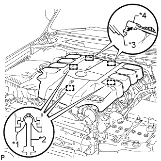
Text in Illustration *1 Grommet *2 Pin *3 Hook *4 Bracket Attach the 2 V-bank cover hooks to the bracket. Then align the 3 V-bank cover grommets with the 3 pins, and press down on the V-bank cover to attach the pins.
-
-
CONNECT CABLE TO NEGATIVE BATTERY TERMINAL
Note
When disconnecting the cable, some systems need to be initialized after the cable is reconnected Click here.
-
INSPECT FOR FUEL LEAK
-
Make sure that there are no fuel leaks after performing maintenance on the fuel system.
-
Connect the GTS to the DLC3.
-
Turn the engine switch on (IG) and turn the GTS on.
Note
Do not start the engine.
-
Enter the following menus: Powertrain / Engine and ECT / Active Test / Control the Fuel Pump / Speed.
-
Check that there are no leaks from the fuel system.
If there are fuel leaks, repair or replace parts as necessary.
-
Turn the engine switch off.
-
Disconnect the GTS from the DLC3.
-
-
-
PERFORM INITIALIZATION
Note
-
Be sure to perform this procedure after reassembling the throttle body with motor assembly or removing and reinstalling any throttle body component.
-
Perform the following procedure after replacing the ECM, throttle body with motor assembly or any throttle body components. The following procedure should also be performed if the throttle body is cleaned.
-
Be sure to perform this procedure after reconnecting the battery cable and replacing the ECM.
-
Disconnect the EFI fuse, wait at least 60 seconds, and then reconnect the fuse.
-
Turn the engine switch on (IG) without operating the accelerator pedal.
Note
If the accelerator pedal is operated, perform the above steps again.
-
Connect the GTS to the DLC3 and clear the DTCs Click here.
-
Start the engine and check that the MIL is not illuminated and that the idle speed is within the specified range when the A/C is switched off after the engine is warmed up.
Standard Condition Engine Idle Speed A/C switched off 650 to 750 rpm Note
-
Be sure to perform this step with all accessories off.
-
Make sure that the shift lever is in N or P.
-
-
Enter the following menus: Powertrain / Engine and ETC / Data List / Throttle Sensor Volt %. Fully depress the accelerator pedal and check that the value is 60% or more.
-
Perform a road test and confirm that there are no abnormalities.
-
-
INSTALL UPPER RADIATOR SUPPORT SEAL
-
Install the upper radiator support seal with the 3 clips.
-
-
INSTALL ENGINE ROOM SIDE COVER RH
-
Install the engine room side cover RH with the 7 clips.
-
-
INSTALL ENGINE ROOM SIDE COVER LH
-
Install the engine room side cover LH with the 7 clips.
-