AIR SWITCHING VALVE (for Bank 1) INSTALLATION

-
INSTALL AIR SWITCHING VALVE ASSEMBLY
-
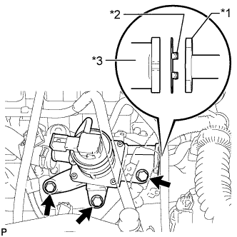
Text in Illustration *1 No. 4 Air Tube *2 Claw *3 Air Switching Valve Install a new gasket and the air switching valve with the 3 bolts.
- Torque:
- 24 N*m { 245 kgf*cm, 18 ft.*lbf }
Note
Make sure the gasket's claws are not caught between the air switching valve and No. 4 air tube.
-
Install the 2 bolts.
- Torque:
- 10 N*m { 102 kgf*cm, 7 ft.*lbf }
-
Connect the wire harness clamp bracket with the bolt.
- Torque:
- 8.0 N*m { 82 kgf*cm, 71 in.*lbf }
-
-
CONNECT NO. 2 AIR INJECTION SYSTEM HOSE
-
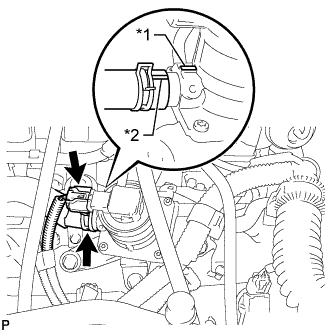
Text in Illustration *1 Protrusion *2 Paint Mark Connect the No. 2 air injection system hose.
Tech Tips
Make sure the direction of the hose clamp is as shown in the illustration.
-
Connect the connector.
-
-
INSTALL V-BANK COVER SUB-ASSEMBLY
-
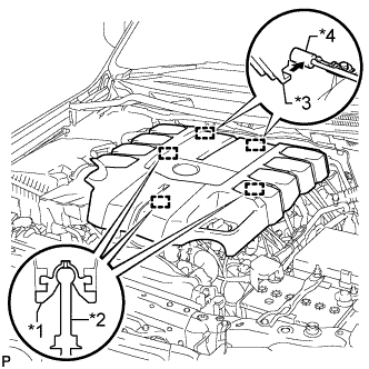
Text in Illustration *1 Grommet *2 Pin *3 Hook *4 Bracket Attach the 2 V-bank cover hooks to the bracket. Then align the 3 V-bank cover grommets with the 3 pins, and press down on the V-bank cover to attach the pins.
-
-
INSTALL ENGINE ROOM SIDE COVER LH
-
Install the engine room side cover LH with the 7 clips.
-