FUEL TANK INSTALLATION

-
INSTALL NO. 1 FUEL TANK HEAT INSULATOR
-
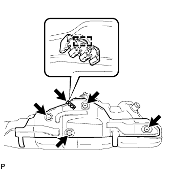
Install the heat insulator with the 4 clips.
-
Install the fuel tube clamp to the heat insulator.
-
-
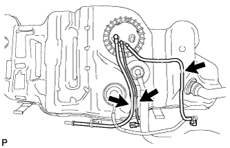
INSTALL FUEL TANK TO FILLER PIPE HOSE
-
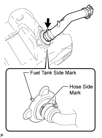
Install the hose to the fuel tank as shown in the illustration.
Tech Tips
-
Align the fuel tank side mark with the hose side mark when installing the hose.
-
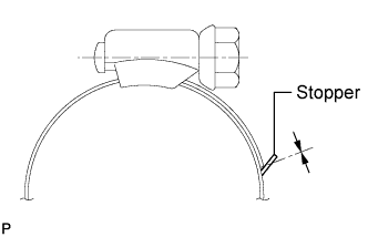
Tighten the hose clamp until the end of the hose clamp contacts the stopper as shown in the illustration.
-
-
-
INSTALL FUEL SUCTION WITH PUMP AND GAUGE TUBE ASSEMBLY
-
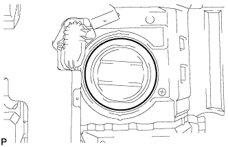
Apply a light coat of gasoline or grease to a new gasket, and install it to the fuel tank.
-
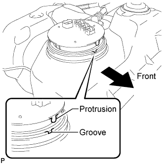
Install the fuel suction with pump and gauge tube into the fuel tank.
Note
Be careful not to bend the arm of the fuel sender gauge.
Tech Tips
Align the protrusion of the fuel suction with pump and gauge tube with the groove of the fuel tank.
-
Put the retainer on the fuel tank. While holding the fuel suction with pump and gauge tube, tighten the retainer 1 complete turn by hand.
-
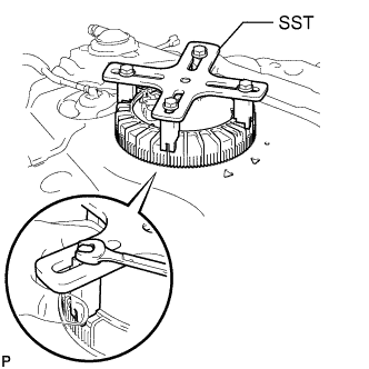
Set SST on the retainer.
- SST
- 09808-14030
Tech Tips
-
Hold the fuel suction tube assembly upright by hand to ensure that the fuel suction tube gasket is not moved out of position.
-
Engage the claws of SST securely with the fuel pump gauge retainer holes to secure SST.
-
Install SST while pressing the claws of SST against the fuel pump gauge retainer (toward the center of SST).
-
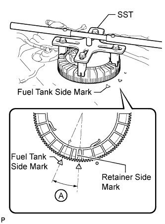
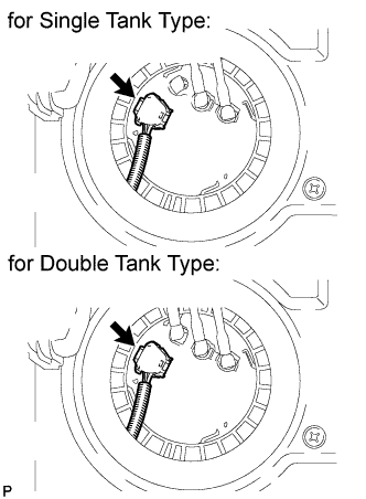
Using SST, tighten the retainer until the mark on the retainer is within range A on the fuel tank, as shown in the illustration.
- SST
- 09808-14030
Tech Tips
Fit the tips of SST onto the ribs of the retainer.
-
-
INSTALL FUEL TANK MAIN TUBE SUB-ASSEMBLY AND FUEL TANK RETURN TUBE SUB-ASSEMBLY (for Single Tank Type)
-
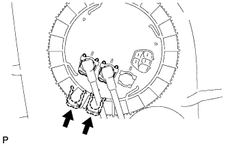
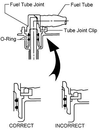
Install the 2 fuel tank tubes with the 2 tube joint clips.
Note
-
Check that there are no scratches or foreign objects on the connecting parts.
-
Check that the fuel tube joints are inserted securely.
-
Check that the tube joint clips are on the collars of the fuel tube joints.
-
After installing the tube joint clips, check that the fuel tube joints cannot be pulled off.
-
-
Install the 2 fuel tank tubes to the fuel tank.
-
-
INSTALL FUEL TANK MAIN TUBE, FUEL TANK RETURN TUBE AND NO. 2 FUEL TANK MAIN TUBE SUB-ASSEMBLY (for Double Tank Type)
-
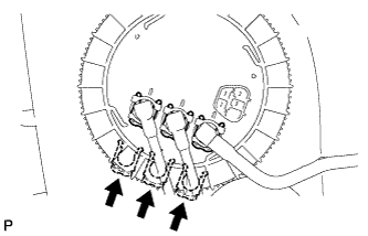
Install the 3 fuel tank tubes with the 3 tube joint clips.
Note
-
Check that there are no scratches or foreign objects on the connecting parts.
-
Check that the fuel tube joints are inserted securely.
-
Check that the tube joint clips are on the collars of the fuel tube joints.
-
After installing the tube joint clips, check that the fuel tube joints cannot be pulled off.
-
-
Install the 3 fuel tank tubes to the fuel tank.
-
-
INSTALL FUEL TANK SUB-ASSEMBLY
-
Set the fuel tank on a transmission jack and raise the fuel tank.
Note
Do not allow the fuel tank to contact the vehicle, especially the differential.
-
Raise the transmission jack.
-
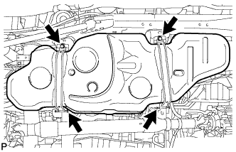
Install the 2 fuel tank bands with the 2 pins and 2 clips.
-
Connect the 2 fuel tank bands with the 2 bolts.
- Torque:
- 40 N*m { 408 kgf*cm, 30 ft.*lbf }
-
-
CONNECT FUEL TANK TO FILLER PIPE HOSE (for Single Tank Type)
-
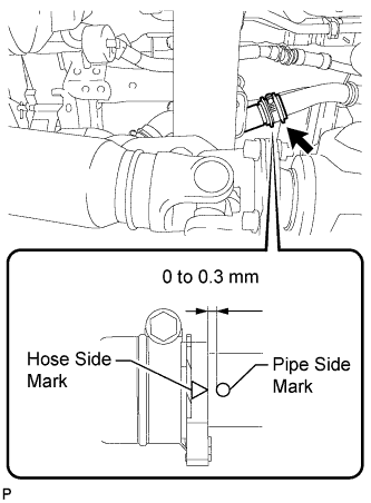
Connect the hose to the filler pipe as shown in the illustration.
Tech Tips
-
Install the hose so that the distance between the fuel tank inlet pipe side mark and fuel tank to filler pipe hose side mark is 0 to 0.3 mm (0 to 0.0118 in.) as shown in the illustration.
-
Tighten the hose clamp until the end of the hose clamp contacts the stopper as shown in the illustration.
-
-
-
CONNECT FUEL TANK TO FILLER PIPE HOSE (for Double Tank Type)
-
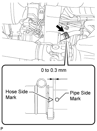
Connect the hose to the filler pipe as shown in the illustration.
Tech Tips
-
Install the hose so that the distance between the fuel tank inlet pipe side mark and fuel tank to filler pipe hose side mark is 0 to 0.3 mm (0 to 0.0118 in.) as shown in the illustration.
-
Tighten the hose clamp until the end of the hose clamp contacts the stopper as shown in the illustration.
-
-
-
CONNECT FUEL TANK BREATHER TUBE (for Single Tank Type)
-
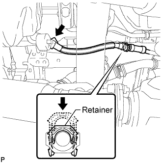
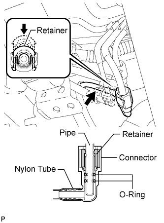
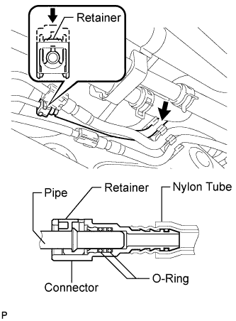
Connect the fuel tank breather tube to the filler pipe and push the retainer.
Tech Tips
Push the parts together firmly until a "click" sound is heard.
Note
-
Before installing the tube connectors to the pipes, check if there is any damage or foreign matter in the connectors.
-
After the connection, check if the connectors and pipes are securely connected by trying to pull them apart.
-
-
Attach the fuel tube clamp.
-
-
CONNECT FUEL TANK BREATHER TUBE (for Double Tank Type)
-
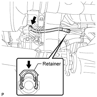
Connect the fuel tank breather tube to the filler pipe and push the retainer.
Tech Tips
Push the parts together firmly until a "click" sound is heard.
Note
-
Before installing the tube connectors to the pipes, check if there is any damage or foreign matter in the connectors.
-
After the connection, check if the connectors and pipes are securely connected by trying to pull them apart.
-
-
Attach the fuel tube clamp.
-
-
CONNECT NO. 2 FUEL MAIN TUBE SUB-ASSEMBLY (for Double Tank Type)
-
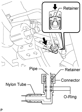
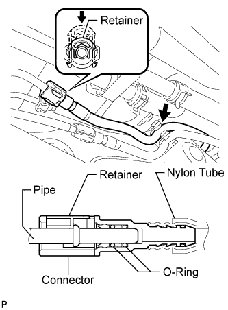
Connect the fuel main tube and push the retainer.
Tech Tips
Push the parts together firmly until a "click" sound is heard.
Note
-
Before installing the tube connectors to the pipes, check if there is any damage or foreign matter in the connectors.
-
After the connection, check if the connectors and pipes are securely connected by trying to pull them apart.
-
-
Attach the fuel tube clamp.
-
-
CONNECT NO. 2 FUEL TANK BREATHER TUBE (for Double Tank Type)
-
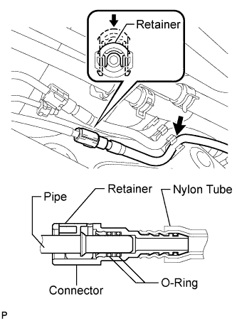
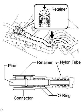
Connect the fuel tank breather tube and push the retainer.
Tech Tips
Push the parts together firmly until a "click" sound is heard.
Note
-
Before installing the tube connectors to the pipes, check if there is any damage or foreign matter in the connectors.
-
After the connection, check if the connectors and pipes are securely connected by trying to pull them apart.
-
-
Attach the fuel tube clamp.
-
-
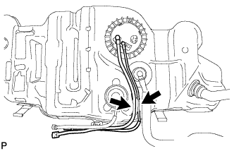
CONNECT FUEL TANK RETURN TUBE (for Single Tank Type)
-
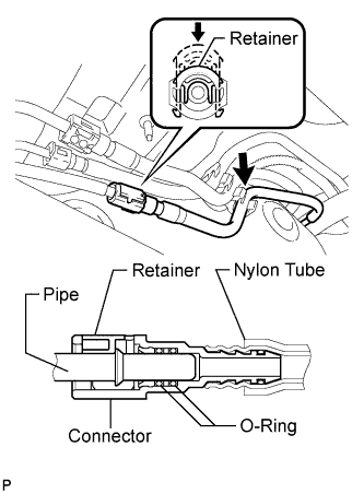
Connect the fuel tank return tube and push the retainer.
Tech Tips
Push the parts together firmly until a "click" sound is heard.
Note
-
Before installing the tube connectors to the pipes, check if there is any damage or foreign matter in the connectors.
-
After the connection, check if the connectors and pipes are securely connected by trying to pull them apart.
-
-
Attach the fuel tube clamp.
-
-
CONNECT FUEL TANK RETURN TUBE (for Double Tank Type)
-
Connect the fuel tank return tube and push the retainer.
Tech Tips
Push the parts together firmly until a "click" sound is heard.
Note
-
Before installing the tube connectors to the pipes, check if there is any damage or foreign matter in the connectors.
-
After the connection, check if the connectors and pipes are securely connected by trying to pull them apart.
-
-
Attach the fuel tube clamp.
-
-
CONNECT NO. 2 FUEL TANK BREATHER TUBE (for Single Tank Type)
-
Connect the fuel tank breather tube and push the retainer.
Tech Tips
Push the parts together firmly until a "click" sound is heard.
Note
-
Before installing the tube connectors to the pipes, check if there is any damage or foreign matter in the connectors.
-
After the connection, check if the connectors and pipes are securely connected by trying to pull them apart.
-
-
Attach the fuel tube clamp.
-
-
CONNECT FUEL TANK MAIN TUBE SUB-ASSEMBLY (for Single Tank Type)
-
Connect the fuel tank main tube and push the retainer.
Tech Tips
Push the parts together firmly until a "click" sound is heard.
Note
-
Before installing the tube connectors to the pipes, check if there is any damage or foreign matter in the connectors.
-
After the connection, check if the connectors and pipes are securely connected by trying to pull them apart.
-
-
Attach the fuel tube clamp.
-
-
CONNECT FUEL TANK MAIN TUBE SUB-ASSEMBLY (for Double Tank Type)
-
Connect the fuel tank main tube and push the retainer.
Tech Tips
Push the parts together firmly until a "click" sound is heard.
Note
-
Before installing the tube connectors to the pipes, check if there is any damage or foreign matter in the connectors.
-
After the connection, check if the connectors and pipes are securely connected by trying to pull them apart.
-
-
Attach the fuel tube clamp.
-
-
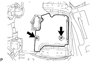
INSTALL NO. 1 FUEL TANK PROTECTOR SUB-ASSEMBLY
-
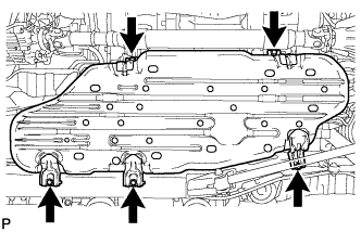
Install the tank protector with the 5 bolts.
- Torque:
- 20 N*m { 204 kgf*cm, 15 ft.*lbf }
-
-
INSTALL FUEL TANK CAP ASSEMBLY
-
INSTALL REAR FLOOR NO. 2 SERVICE HOLE COVER
-
Connect the fuel pump and fuel sender gauge connector.
-
Install the service hole cover with new butyl tape.
-
Install the air duct and 2 screws.
-
-
INSTALL FRONT FLOOR CARPET ASSEMBLY
-
INSTALL REAR SEAT ASSEMBLY
-
Install the rear No. 1 seat assembly and rear No. 2 seat assembly Click here.
-
-
CONNECT CABLE TO NEGATIVE BATTERY TERMINAL
Note
When disconnecting the cable, some systems need to be initialized after the cable is reconnected Click here.
-
ADD FUEL
-
INSPECT FOR FUEL LEAK
-
Connect the intelligent tester to the DLC3.
-
Turn the engine switch on (IG) and intelligent tester on.
Note
Do not start the engine.
-
Enter the following menus: Powertrain / Engine and ECT / Active Test / Control the Fuel Pump Speed Control.
-
Check that there are no fuel leaks after doing maintenance anywhere on the fuel system.
-