FUEL INJECTOR REMOVAL

-
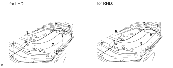
REMOVE ENGINE ROOM SIDE COVER LH
-
Remove the 7 clips and engine room side cover LH.
-
-
REMOVE ENGINE ROOM SIDE COVER RH
-
Remove the 7 clips and engine room side cover RH.
-
-
REMOVE UPPER RADIATOR SUPPORT SEAL
-
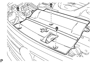
Remove the 3 clips and upper radiator support seal.
-
-
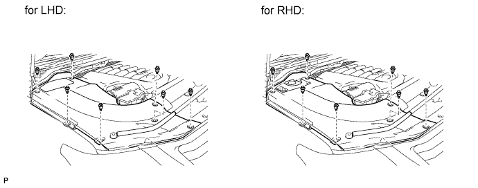
REMOVE V-BANK COVER SUB-ASSEMBLY
-
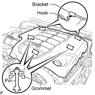
Raise the front of the V-bank cover to detach the 3 pins. Then remove the 2 V-bank cover hooks from the bracket, and remove the V-bank cover.
-
-
DISCHARGE FUEL SYSTEM PRESSURE
-
Discharge the fuel system pressure Click here.
-
-
DISCONNECT CABLE FROM NEGATIVE BATTERY TERMINAL
Note
-
w/ Navigation System:
After the engine switch is turned off, the HDD navigation system requires approximately 6 minutes to record various types of memory and settings. As a result, after turning the engine switch off, wait 6 minutes or more before disconnecting the cable from the negative (-) battery terminal.
-
When disconnecting the cable, some systems need to be initialized after the cable is reconnected Click here.
-
-
REMOVE AIR CLEANER HOSE ASSEMBLY
-
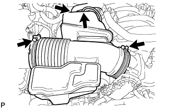
Disconnect the vacuum hose and No. 2 ventilation hose.
-
Loosen the 2 hose clamps.
-
Remove the air cleaner hose.
-
-
REMOVE NO. 1 ENGINE COVER SUB-ASSEMBLY
-
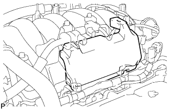
Remove the No. 1 engine cover sub-assembly.
-
-
REMOVE NO. 3 ENGINE COVER
-
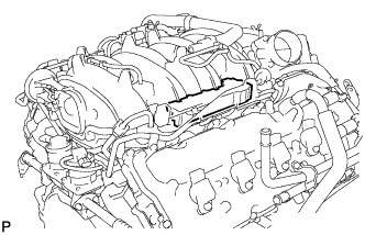
Remove the No. 3 engine cover.
-
-
DISCONNECT NO. 2 FUEL TUBE
-
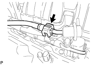
Disconnect the No. 2 fuel tube from the fuel pressure regulator Click here.
-
-
DISCONNECT NO. 1 FUEL TUBE
-
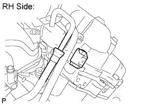
RH Side:
Disconnect the No. 1 fuel tube from the fuel delivery pipe RH (for metallic type) Click here.
- SST
- 09268-21011
-
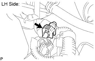
LH Side:
Disconnect the No. 1 fuel tube from the fuel delivery pipe LH Click here.
-
-
DISCONNECT NO. 1 FUEL HOSE
-
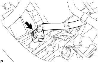
Disconnect the fuel hose from the fuel delivery pipe LH Click here.
-
-
REMOVE FUEL DELIVERY PIPE SUB-ASSEMBLY RH
-
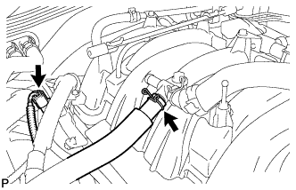
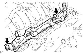
Disconnect the ventilation hose and No. 6 wire harness connector.
-
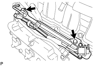
Remove the 2 bolts and fuel delivery pipe RH.
Note
When removing the delivery pipe, hold the pipe by both ends and pull it straight upward.
-
Remove the 2 delivery pipe spacers and 4 insulators from the cylinder head RH.
-
-
REMOVE FUEL DELIVERY PIPE SUB-ASSEMBLY LH
-
Disconnect the No. 7 wire harness connector.
-
Remove the 2 bolts and fuel delivery pipe LH.
Note
When removing the delivery pipe, hold the pipe by both ends and pull it straight upward.
-
Remove the 2 delivery pipe spacers and 4 insulators from the cylinder head LH.
-
-
REMOVE FUEL INJECTOR ASSEMBLY
-
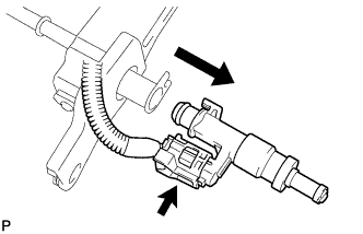
Remove the fuel injector from the fuel delivery pipe, and then disconnect the injector connector.
Note
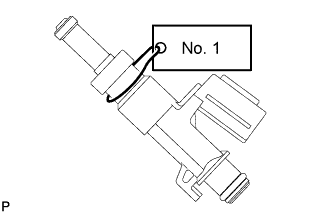
For reinstallation, attach a tag or label to the injector shaft.
-
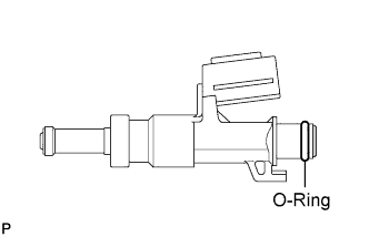
Remove the O-ring from the fuel injector.
-
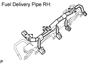
Detach the 3 clamps and then remove the No. 6 wire harness from the delivery pipe RH.
-
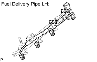
Detach the 3 clamps and then remove the No. 7 wire harness from the delivery pipe LH.
-