FUEL INJECTOR INSTALLATION

-
INSTALL FUEL INJECTOR ASSEMBLY
-
Attach the 3 clamps to install the No. 6 wire harness to the fuel delivery pipe.
-
Attach the 3 clamps to install the No. 7 wire harness to the No. 2 fuel delivery pipe.
-
Apply gasoline or spindle oil to a new O-ring and install the O-ring to the injector.
Note
Make sure that there is no damage or foreign material in the groove of the injector when installing the O-ring.
-
Connect the injector connector.
-
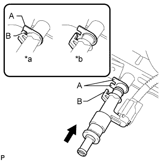
Text in Illustration *a CORRECT *b INCORRECT Install the injector to the delivery pipe as shown in the illustration.
Note
-
Make sure that there are no scratches or foreign matter in or around the insertion hole of the delivery pipe.
-
When inserting the injector, be careful not to damage the O-ring.
-
Attach the part of the injector labeled B between the parts of the delivery pipe labeled A.
-
-
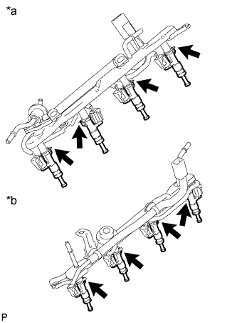
Text in Illustration *a Fuel Delivery Pipe *b No. 2 Fuel Delivery Pipe Check that each injector is installed to the delivery pipe facing the direction shown in the illustration.
-
-
INSTALL NO. 2 FUEL DELIVERY PIPE SUB-ASSEMBLY
-
Install the 2 delivery pipe spacers and 4 insulators to the cylinder head LH.
-
Install the delivery pipe together with the injectors to the cylinder head LH.
-
Install the 2 bolts.
- Torque:
- 21 N*m { 214 kgf*cm, 15 ft.*lbf }
Note
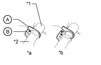
Make sure that the part of the injector labeled B is between the parts of the delivery pipe labeled A.
Text in Illustration *1 Fuel Delivery Pipe *2 Fuel Injector *a CORRECT *b INCORRECT -
Connect the No. 7 wire harness connector.
-
-
INSTALL FUEL DELIVERY PIPE SUB-ASSEMBLY
-
Install the 2 delivery pipe spacers and 4 insulators to the cylinder head RH.
-
Install the delivery pipe together with the injectors to the cylinder head RH.
-
Install the 2 bolts.
- Torque:
- 21 N*m { 214 kgf*cm, 15 ft.*lbf }
Note
Make sure that the part of the injector labeled B is between the parts of the delivery pipe labeled A.
Text in Illustration *1 Fuel Delivery Pipe *2 Fuel Injector *a CORRECT *b INCORRECT -
Connect the No. 6 wire harness connector.
-
-
CONNECT FUEL HOSE
-
Connect the fuel hose to the fuel No. 2 fuel delivery pipe Click here.
-
Attach the clamp.
-
-
CONNECT WIRE HARNESS AND HOSE
-
Connect the purge VSV connector.
-
Connect the purge line hose to the purge VSV.
-
Connect the vacuum switching valve connector (for ACIS).
-
-
CONNECT FUEL TUBE SUB-ASSEMBLY
-
Connect the fuel tube to the No. 2 fuel delivery pipe Click here.
-
Connect the fuel tube to the fuel delivery pipe Click here.
-
-
CONNECT NO. 2 FUEL TUBE SUB-ASSEMBLY
-
Connect the No. 2 fuel tube to the fuel pressure regulator Click here.
-
-
INSTALL EGR VALVE BRACKET
-
Install the EGR valve bracket with the 3 bolts.
- Torque:
- 21 N*m { 214 kgf*cm, 15 ft.*lbf }
-
Attach the 2 wire harness clamps and PCV hose clamp.
-
-
INSTALL NO. 5 WATER BY-PASS PIPE
-
Install the No. 5 water by-pass pipe with the 2 bolts and connect the 2 water by-pass hoses.
- Torque:
- 21 N*m { 214 kgf*cm, 15 ft.*lbf }
-
-
INSTALL AIR SWITCHING VALVE ASSEMBLY (for Bank 2)
-
INSTALL AIR SWITCHING VALVE ASSEMBLY (for Bank 1)
-
INSTALL AIR CLEANER CAP AND HOSE
-
Install the air cleaner cap and hose, and then tighten the hose clamp.
- Torque:
- 2.5 N*m { 25 kgf*cm, 22 in.*lbf }
-
Attach the 4 clamps.
-
Connect the mass air flow meter connector and attach the clamp.
-
Connect the No. 2 PCV hose and No. 1 air hose.
-
-
CONNECT CABLE TO NEGATIVE BATTERY TERMINAL
Note
When disconnecting the cable, some systems need to be initialized after the cable is reconnected Click here.
-
ADD ENGINE COOLANT
-
Add engine coolant.
Standard capacity 16.5 liters (17.4 US qts, 14.5 Imp. qts) Note
Do not substitute plain water for engine coolant.
Tech Tips
-
TOYOTA vehicles are filled with TOYOTA SLLC at the factory. In order to avoid damage to the engine cooling system and other technical problems, only use TOYOTA SLLC or similar high quality ethylene glycol based non-silicate, non-amine, non-nitrite, non-borate coolant with long-life hybrid organic acid technology (coolant with long-life hybrid organic acid technology consists of a combination of low phosphates and organic acids).
-
Press the No. 1 and No. 2 radiator hoses several times by hand, and then check the coolant level. If the coolant level is low, add coolant.
-
-
Slowly pour coolant into the radiator reservoir until it reaches the F line.
-
Install the reservoir cap.
-
Install the radiator cap.*1
-
Start the engine and stop it immediately.*2
-
Allow approximately 10 seconds to pass. Then remove the radiator cap and check the coolant level. If the coolant level has decreased, add coolant.*3
-
Repeat steps *1, *2 and *3 until the coolant level does not decrease.
Tech Tips
Be sure to perform this step while the engine is cold, as air in the No. 1 radiator hose will flow into the radiator if the engine is warmed up and the thermostat opens.
-
Install the radiator cap.*4
-
Set the air conditioning as follows.*5
Item Condition Fan speed Any setting except off Temperature Toward WARM Air conditioning switch Off -
Start the engine, warm it up until the thermostat opens, and then continue to run the engine for several minutes to circulate the coolant.*6
CAUTION:
-
Wear protective gloves. Hot areas on the parts may injure your hands.
-
Be careful of the fan.
-
Be careful as the engine, radiator and radiator hoses are hot and can cause burns.
Note
-
Immediately after starting the engine, if the radiator reservoir does not have any coolant, perform the following: 1) stop the engine, 2) wait until the coolant has cooled down, and 3) add coolant until the coolant is filled to the F line.
-
Do not start the engine when there is no coolant in the radiator reservoir.
-
Pay attention to the needle of the engine coolant temperature receiver gauge. Make sure that the needle does not show an abnormally high temperature.
-
If there is not enough coolant, the engine may burn out or overheat.
Tech Tips
-
Press the No. 1 and No. 2 radiator hoses several times by hand to bleed air while warming up the engine.
-
The thermostat opening timing can be confirmed by pressing the No. 2 radiator hose by hand and checking when the engine coolant starts to flow inside the hose.
-
-
Stop the engine, wait until the engine coolant cools down to ambient temperature. Then remove the radiator cap and check the coolant level.*7
CAUTION:
Do not remove the radiator cap while the engine and radiator are still hot. Pressurized, hot engine coolant and steam may be released and cause serious burns.
-
If the coolant level has decreased, add coolant and warm up the engine until the thermostat opens.*8
-
If the coolant level has not decreased, check that the coolant level in the radiator reservoir is at the F line.
If the coolant level is below the F line, repeat steps *4 through *8.
If the coolant level is above the F line, drain coolant until the coolant level reaches the F line.
-
-
INSPECT FOR FUEL LEAK
-
Make sure that there are no fuel leaks after performing maintenance on the fuel system.
-
Connect the GTS to the DLC3.
-
Turn the engine switch on (IG) and turn the GTS on.
Note
Do not start the engine.
-
Enter the following menus: Powertrain / Engine and ECT / Active Test / Control the Fuel Pump / Speed.
-
Check that there are no leaks from the fuel system.
If there are fuel leaks, repair or replace parts as necessary.
-
Turn the engine switch off.
-
Disconnect the GTS from the DLC3.
-
-
-
INSPECT FOR COOLANT LEAK
CAUTION:
To avoid being burned, do not remove the radiator reservoir cap while the engine and radiator are still hot. Thermal expansion may cause hot engine coolant and steam to blow out from the radiator.
-
Fill the radiator with engine coolant, and then attach a radiator cap tester.
-
Warm up the engine.
-
Using the radiator cap tester, increase the pressure inside the radiator to 123 kPa (1.3 kgf/cm2, 18 psi), and then check that the pressure does not drop.
If the pressure drops, check the hoses, radiator and engine water pump for leakage. If there are no signs or traces of external engine coolant leakage, check the heater core, cylinder block and head.
-
-
INSTALL NO. 1 ENGINE UNDER COVER SUB-ASSEMBLY
-
Install the No. 1 engine under cover sub-assembly with the 10 bolts.
- Torque:
- 29 N*m { 296 kgf*cm, 21 ft.*lbf }
-
-
INSTALL FRONT FENDER SPLASH SHIELD SUB-ASSEMBLY LH
-
Push in the clip to install the front fender splash shield sub-assembly LH.
-
Install the 3 bolts and 2 screws.
-
-
INSTALL FRONT FENDER SPLASH SHIELD SUB-ASSEMBLY RH
Tech Tips
Use the same procedure described for the LH side.
-
INSTALL V-BANK COVER SUB-ASSEMBLY
-
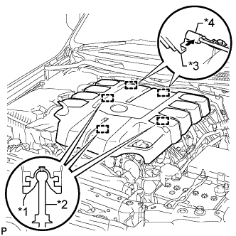
Text in Illustration *1 Grommet *2 Pin *3 Hook *4 Bracket Attach the 2 V-bank cover hooks to the bracket. Then align the 3 V-bank cover grommets with the 3 pins, and press down on the V-bank cover to attach the pins.
-
-
INSTALL UPPER RADIATOR SUPPORT SEAL
-
Install the upper radiator support seal with the 3 clips.
-
-
INSTALL ENGINE ROOM SIDE COVER RH
-
Install the engine room side cover RH with the 7 clips.
-
-
INSTALL ENGINE ROOM SIDE COVER LH
-
Install the engine room side cover LH with the 7 clips.
-