FUEL INJECTOR REMOVAL

-
DISCHARGE FUEL SYSTEM PRESSURE
CAUTION:
-
Do not disconnect any part of the fuel system until you have discharged the fuel system pressure.
-
After discharging the fuel pressure, place a cloth or equivalent over fittings as you separate them to reduce the risk of fuel spray on yourself or in the engine compartment.
-
Disconnect the fuel pump ECU connector Click here.
-
Start the engine. After the engine stops, turn the engine switch off.
Tech Tips
DTC P0171/0174 (system too lean) may be stored.
-
Crank the engine again, and then check that the engine does not start.
-
Loosen the fuel tank cap, and then discharge the pressure in the fuel tank completely.
-
Disconnect the cable from the negative (-) battery terminal.
Note
-
w/ Navigation System:
After the engine switch is turned off, the HDD navigation system requires approximately 6 minutes to record various types of memory and settings. As a result, after turning the engine switch off, wait 6 minutes or more before disconnecting the cable from the negative (-) battery terminal.
-
When disconnecting the cable, some systems need to be initialized after the cable is reconnected Click here.
-
-
Connect the fuel pump ECU connector Click here.
-
-
DISCONNECT CABLE FROM NEGATIVE BATTERY TERMINAL
Note
-
w/ Navigation System:
After the engine switch is turned off, the HDD navigation system requires approximately 6 minutes to record various types of memory and settings. As a result, after turning the engine switch off, wait 6 minutes or more before disconnecting the cable from the negative (-) battery terminal.
-
When disconnecting the cable, some systems need to be initialized after the cable is reconnected Click here.
-
-
REMOVE FRONT FENDER SPLASH SHIELD SUB-ASSEMBLY LH
-
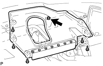
Remove the 3 bolts and 2 screws.
-
Turn the clip indicated by the arrow in the illustration to remove the front fender splash shield sub-assembly LH.
-
-
REMOVE FRONT FENDER SPLASH SHIELD SUB-ASSEMBLY RH
Tech Tips
Use the same procedure described for the LH side.
-
REMOVE NO. 1 ENGINE UNDER COVER SUB-ASSEMBLY
-
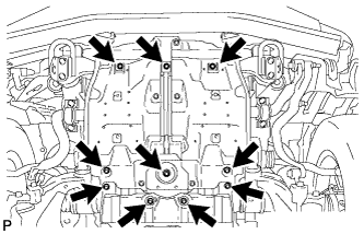
Remove the 10 bolts and No. 1 engine under cover sub-assembly.
-
-
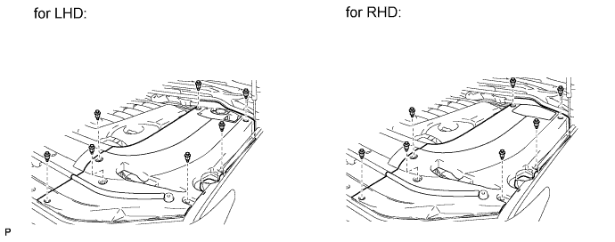
REMOVE ENGINE ROOM SIDE COVER LH
-
Remove the 7 clips and engine room side cover LH.
-
-
REMOVE ENGINE ROOM SIDE COVER RH
-
Remove the 7 clips and engine room side cover RH.
-
-
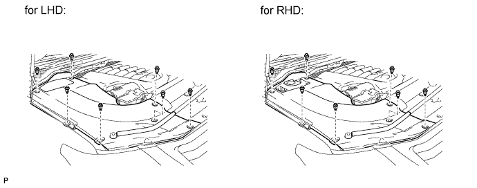
REMOVE UPPER RADIATOR SUPPORT SEAL
-
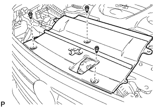
Remove the 3 clips and upper radiator support seal.
-
-
REMOVE V-BANK COVER SUB-ASSEMBLY
-
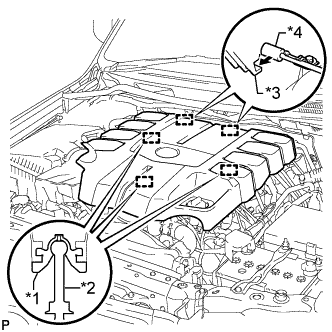
Text in Illustration *1 Grommet *2 Pin *3 Hook *4 Bracket Raise the front of the V-bank cover to detach the 3 pins. Then remove the 2 V-bank cover hooks from the bracket, and remove the V-bank cover.
-
-
REMOVE AIR CLEANER CAP AND HOSE
-
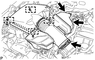
Disconnect the No. 2 PCV hose and No. 1 air hose.
-
Disconnect the mass air flow meter connector and detach the clamp.
-
Detach the 4 clamps.
-
Loosen the hose clamp and remove the air cleaner cap and hose.
-
-
DRAIN ENGINE COOLANT
CAUTION:
Do not remove the radiator cap while the engine and radiator are still hot. Pressurized, hot engine coolant and steam may be released and cause serious burns.
-
Loosen the radiator drain cock plug.
-
Remove the radiator cap and drain the coolant.
Tech Tips
Collect the coolant in a container and dispose of it according to the regulations in your area.
-
Loosen the 2 cylinder block drain cock plugs and drain the coolant from the engine.
-
Tighten the 2 cylinder block drain cock plugs.
- Torque:
- 13 N*m { 130 kgf*cm, 9 ft.*lbf }
-
Tighten the radiator drain cock plug by hand.
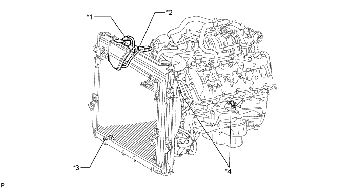
Text in Illustration *1 Reservoir Cap *2 Radiator Cap *3 Radiator Drain Cock Plug *4 Cylinder Block Drain Cock Plug
-
-
REMOVE AIR SWITCHING VALVE ASSEMBLY (for Bank 1)
-
REMOVE AIR SWITCHING VALVE ASSEMBLY (for Bank 2)
-
REMOVE NO. 5 WATER BY-PASS PIPE
-
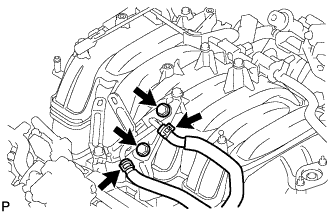
Disconnect the 2 water by-pass hoses and remove the 2 bolts and No. 5 water by-pass pipe.
-
-
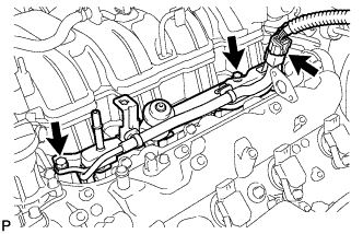
REMOVE EGR VALVE BRACKET
-
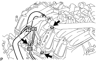
Detach the 2 wire harness clamps and PCV hose clamp.
-
Remove the 3 bolts and EGR valve bracket.
-
-
DISCONNECT NO. 2 FUEL TUBE SUB-ASSEMBLY
-
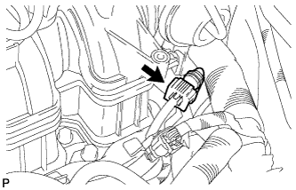
Disconnect the No. 2 fuel tube from the fuel pressure regulator Click here.
-
-
DISCONNECT FUEL TUBE SUB-ASSEMBLY
-
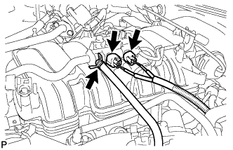
Disconnect the fuel tube from the fuel delivery pipe Click here.
-
Disconnect the fuel tube from the No. 2 fuel delivery pipe Click here.
-
-
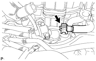
DISCONNECT WIRE HARNESS AND HOSE
-
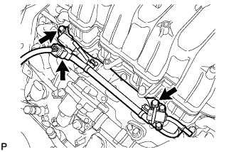
Disconnect the purge VSV connector.
-
Disconnect the purge line hose from the purge VSV.
-
Disconnect the vacuum switching valve connector (for ACIS).
-
-
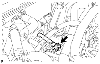
DISCONNECT FUEL HOSE
-
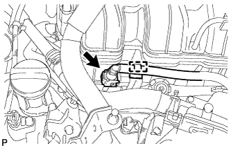
Detach the clamp.
-
Disconnect the fuel hose from the No. 2 fuel delivery pipe Click here.
-
-
REMOVE FUEL DELIVERY PIPE SUB-ASSEMBLY
-
Disconnect the No. 6 wire harness connector.
-
Remove the 2 bolts and fuel delivery pipe.
Note
When removing the delivery pipe, hold the pipe by both ends and pull it straight upward.
-
Remove the 2 delivery pipe spacers and 4 insulators from the intake manifold.
-
-
REMOVE NO. 2 FUEL DELIVERY PIPE SUB-ASSEMBLY
-
Disconnect the No. 7 wire harness connector.
-
Remove the 2 bolts and No. 2 fuel delivery pipe.
Note
When removing the delivery pipe, hold the pipe by both ends and pull it straight upward.
-
Remove the 2 delivery pipe spacers and 4 insulators from the intake manifold.
-
-
REMOVE FUEL INJECTOR ASSEMBLY
-
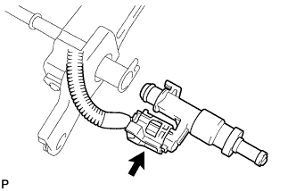
Text in Illustration *1 No. 1 Remove the fuel injector from the fuel delivery pipe, and then disconnect the injector connector.
Note
For reinstallation, attach a tag or label to the injector shaft.
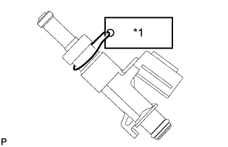
-
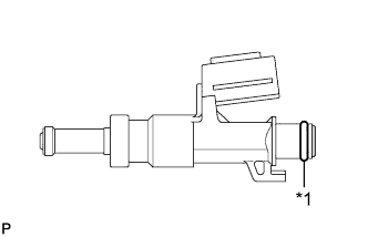
Text in Illustration *1 O-ring Remove the O-ring from the fuel injector.
-
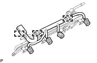
Detach the 3 clamps and then remove the No. 6 wire harness from the fuel delivery pipe.
-
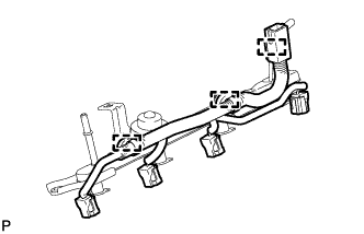
Detach the 3 clamps and then remove the No. 7 wire harness from the No. 2 fuel delivery pipe.
-