ENGINE UNIT INSTALLATION

-
INSTALL NOISE FILTER
-
RH:
Install the noise filter to the cylinder head cover with the bolt.
- Torque:
- 7.0 N*m { 71 kgf*cm, 62 in.*lbf }
-
LH:
Install the noise filter to the cylinder head cover with the bolt.
- Torque:
- 7.0 N*m { 71 kgf*cm, 62 in.*lbf }
-
-
INSTALL IGNITION COIL ASSEMBLY
-
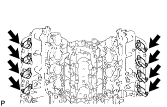
Install the 8 ignition coils with the 8 bolts.
- Torque:
- 10 N*m { 102 kgf*cm, 7 ft.*lbf }
-
-
INSTALL FRONT NO. 1 ENGINE MOUNTING BRACKET LH
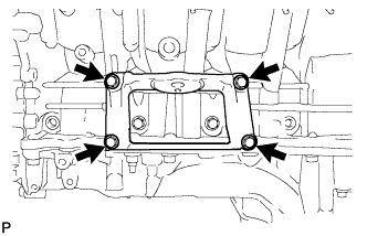
-
Install the mounting bracket with the 4 bolts.
- Torque:
- 35 N*m { 357 kgf*cm, 26 ft.*lbf }
-
-
INSTALL FRONT NO. 1 ENGINE MOUNTING BRACKET RH
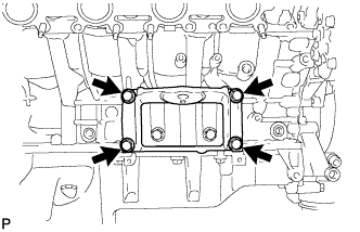
-
Install the mounting bracket with the 4 bolts.
- Torque:
- 35 N*m { 357 kgf*cm, 26 ft.*lbf }
-
-
INSTALL CYLINDER BLOCK WATER DRAIN COCK SUB-ASSEMBLY
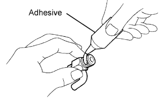
-
Apply adhesive to 2 or 3 threads of the drain cocks.
Adhesive Toyota Genuine Adhesive 1344, Three Bond 1344 or equivalent -
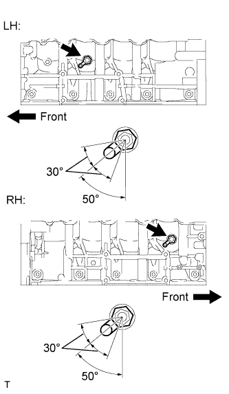
Install the water drain cocks as shown in the illustration.
- Torque:
- 30 N*m { 306 kgf*cm, 22 ft.*lbf }
Note
-
Do not rotate the drain cocks more than 1 revolution (360°) after tightening the drain cocks to the specified torque.
-
Do not loosen the drain cocks to adjust them. If an adjustment is necessary, remove the drain cocks and reinstall them.
-
Install the water drain cock plugs to the water drain cocks.
- Torque:
- 13 N*m { 130 kgf*cm, 10 ft.*lbf }
-
-
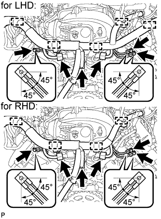
INSTALL KNOCK SENSOR
-
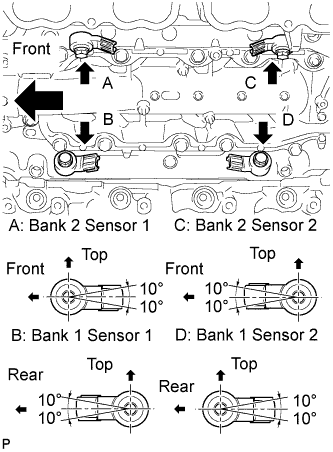
Install the 4 sensors with the 4 bolts so that the sensors are angled as shown in the illustration.
- Torque:
- 20 N*m { 204 kgf*cm, 15 ft.*lbf }
Note
The acceptable installation angle of the sensor is between 10° upward and downward from the horizontal position.
-
-
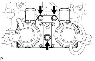
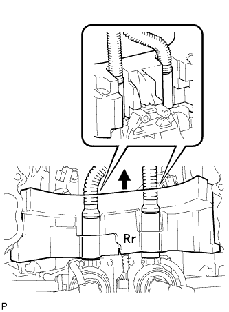
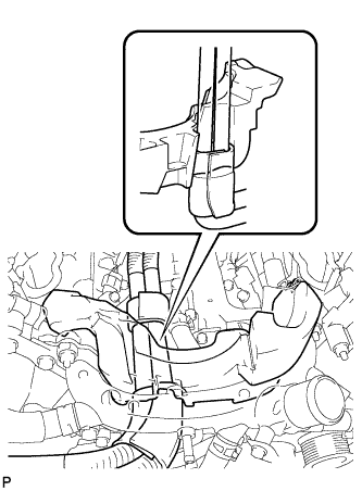
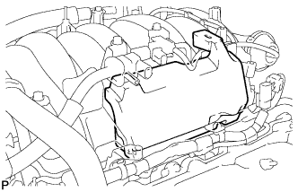
INSTALL SEPARATOR CASE
-
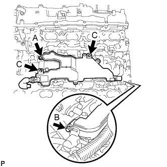
After inserting the pipe on the rear of the separator case into the oil return pipe and the pipe on the front into the ventilation pipe, temporarily install bolt A.
-
Temporarily install bolt B and tighten bolt A.
- Torque:
- 10 N*m { 102 kgf*cm, 7 ft.*lbf }
-
Install the bolts labeled C.
- Torque:
- 10 N*m { 102 kgf*cm, 7 ft.*lbf }
-
Tighten bolt B.
- Torque:
- 10 N*m { 102 kgf*cm, 7 ft.*lbf }
Standard Bolt Item Length Thread Diameter Bolt A 25 mm (0.984 in.) 6 mm (0.236 in.) Bolt B and C 16 mm (0.630 in.) 6 mm (0.236 in.)
-
-
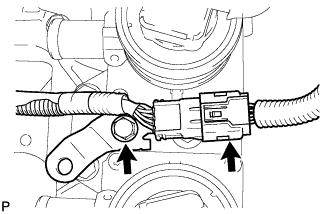
INSTALL SENSOR WIRE
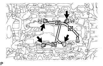
-
Connect the 3 clamps and 4 knock sensor connectors.
-
-
INSTALL NO. 3 AIR TUBE (w/ Secondary Air Injection System)
-
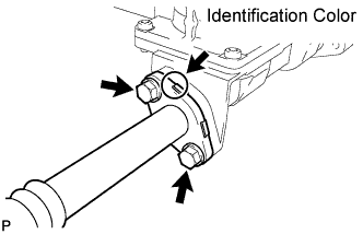
Install a new gasket and the No. 3 air tube with the 2 bolts.
- Torque:
- 10 N*m { 102 kgf*cm, 7 ft.*lbf }
Tech Tips
The identification color on the flange is orange.
Note
Make sure the claws on the gasket are not caught between the air tube and air switching valve.
-
-
INSTALL NO. 2 AIR TUBE (w/ Secondary Air Injection System)
-
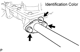
Install a new gasket and the No. 2 air tube with the 2 bolts.
- Torque:
- 10 N*m { 102 kgf*cm, 7 ft.*lbf }
Tech Tips
The identification color on the flange is blue.
Note
Make sure the claws on the gasket are not caught between the air tube and air switching valve.
-
-
INSTALL AIR SWITCHING VALVE ASSEMBLY (w/ Secondary Air Injection System)
-
Install the air switching valve with the 3 bolts.
- Torque:
- 21 N*m { 214 kgf*cm, 15 ft.*lbf }
-
Connect the 2 air switching valve connectors.
-
Install the bracket with the bolt.
- Torque:
- 8.0 N*m { 82 kgf*cm, 71 in.*lbf }
-
Connect the knock sensor connector.
-
-
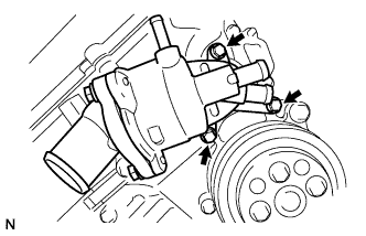
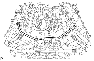
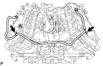
INSTALL WATER BY-PASS PIPE SUB-ASSEMBLY
-
Install the water by-pass pipe with the 2 bolts.
- Torque:
- 10 N*m { 102 kgf*cm, 7 ft.*lbf }
-
-
INSTALL WATER INLET HOUSING
-
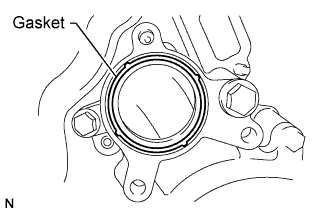
Install a new gasket to the timing chain cover.
-
Install the water inlet with the 3 bolts.
- Torque:
- 21 N*m { 214 kgf*cm, 15 ft.*lbf }
-
-
INSTALL AIR PIPE SUB-ASSEMBLY (w/ Secondary Air Injection System)
-
Install the 2 No. 1 air hoses and air pipe with the 2 bolts.
- Torque:
- 10 N*m { 102 kgf*cm, 7 ft.*lbf }
-
-
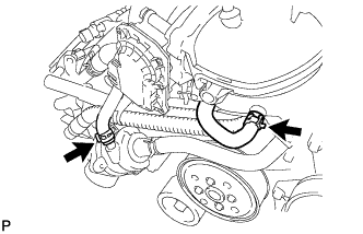
INSTALL FRONT WATER BY-PASS JOINT
-
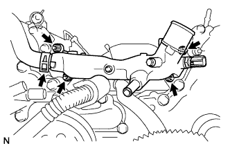
Install 2 new gaskets and the water by-pass joint with the 4 nuts.
- Torque:
- 21 N*m { 214 kgf*cm, 15 ft.*lbf }
-
Connect the No. 2 water by-pass hose to the water by-pass joint.
-
-
INSTALL NO. 1 WATER BY-PASS HOSE
-
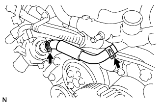
Install the No. 1 water by-pass hose by connecting the hose to the water inlet housing and front water by-pass joint.
-
-
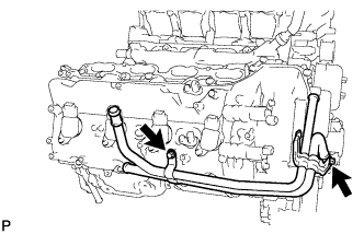
INSTALL NO. 2 WATER BY-PASS PIPE SUB-ASSEMBLY (w/ Oil Cooler)
-
Connect the 4 hoses.
-
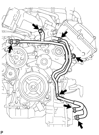
Install the water by-pass pipe with the 3 bolts.
- Torque:
- 10 N*m { 102 kgf*cm, 7 ft.*lbf }
-
-
INSTALL NO. 1 ENGINE COVER
Tech Tips
-
Align the No. 1 engine cover cutouts with the air tube.
-
Align the No. 1 engine cover with the air switching valve surface and cylinder head wall.
Note
Make sure that the No. 1 engine cover is flush with the top surface of the intake port of the cylinder head for bank 1 and bank 2.
-
-
INSTALL NO. 2 ENGINE COVER
Tech Tips
-
Align the No. 2 engine cover cutout with the air tube.
-
Align the No. 2 engine cover with the front water by-pass joint and cylinder head wall.
Note
Make sure that the No. 2 engine cover is flush with the top surface of the intake port of the cylinder head.
-
-
INSTALL NO. 1 FUEL TUBE
-
INSTALL NO. 2 FUEL TUBE
-
Install the No. 2 fuel tube with the 2 bolts.
- Torque:
- 10 N*m { 102 kgf*cm, 7 ft.*lbf }
-
-
INSTALL INTAKE MANIFOLD
-
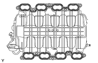
Place 2 new gaskets on the intake manifold.
-
Place the intake manifold on the cylinder head.
-
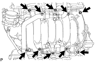
Install and uniformly tighten the 8 bolts and 2 nuts in several steps.
- Torque:
- 21 N*m { 214 kgf*cm, 15 ft.*lbf }
-
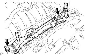
Install the wire bracket to the intake manifold with the bolt.
- Torque:
- 8.0 N*m { 82 kgf*cm, 71 in.*lbf }
-
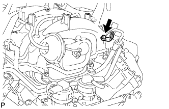
Connect the No. 1 ventilation hose.
-
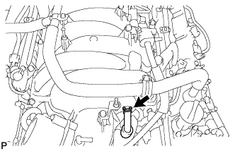
Connect the 2 water by-pass hoses.
-
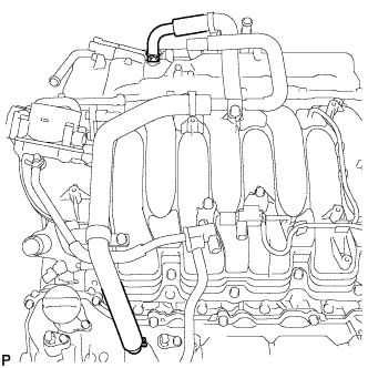
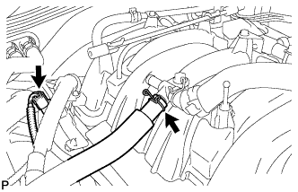
Connect the ventilation hose to the ventilation pipe of the cylinder head cover LH and RH.
-
-
INSTALL FUEL INJECTOR ASSEMBLY
-
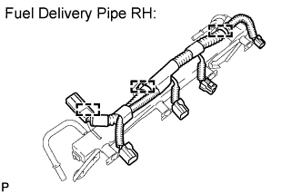
Attach the 3 clamps to install the No. 6 wire harness to the delivery pipe RH.
-
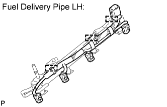
Attach the 3 clamps to install the No. 7 wire harness to the delivery pipe LH.
-
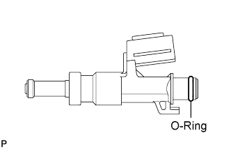
Apply gasoline or spindle oil to a new O-ring and install it to the injector.
Note
Make sure that there is no damage or foreign material in the groove of the injector when installing the O-ring.
-
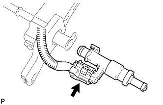
Connect the injector connector.
-
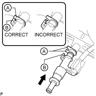
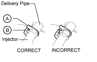
Install the injector to the delivery pipe as shown in the illustration.
Note
-
Make sure that there are no scratches or foreign matter in or around the insertion hole of the delivery pipe.
-
When inserting the injector, be careful not to damage the O-ring.
-
Attach the part of the injector labeled B between the parts of the delivery pipe labeled A.
-
-
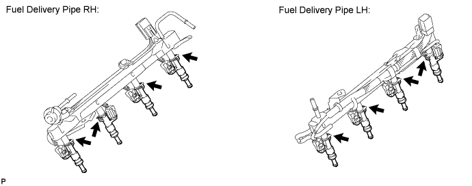
Check that each injector is installed to the delivery pipe facing the direction shown in the illustration.
-
-
INSTALL FUEL DELIVERY PIPE SUB-ASSEMBLY RH
-
Install the 2 delivery pipe spacers and 4 insulators to the cylinder head RH.
-
Install the delivery pipe (with injectors) to the cylinder head RH.
-
Install the 2 bolts.
- Torque:
- 21 N*m { 214 kgf*cm, 15 ft.*lbf }
Note
Make sure that the part of the injector labeled B is between the parts of the delivery pipe labeled A.
-
Connect the No. 6 wire harness connector.
-
Connect the ventilation hose.
-
-
INSTALL FUEL DELIVERY PIPE SUB-ASSEMBLY LH
-
Install the 2 delivery pipe spacers and 4 insulators to the cylinder head LH.
-
Install the delivery pipe (with injectors) to the cylinder head LH.
-
Install the 2 bolts.
- Torque:
- 21 N*m { 214 kgf*cm, 15 ft.*lbf }
Note
Make sure that the part of the injector labeled B is between the parts of the delivery pipe labeled A.
-
Connect the No. 7 wire harness connector.
-
-
CONNECT NO. 1 FUEL TUBE
-
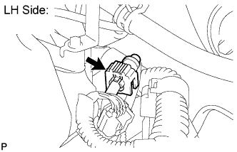
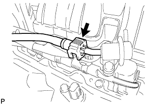
LH Side:
Connect the No. 1 fuel tube to the delivery pipe LH Click here.
-
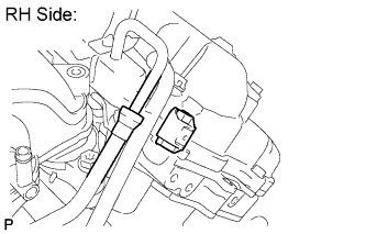
RH Side:
Connect the No. 1 fuel tube to the delivery pipe RH (for metallic type) Click here.
-
-
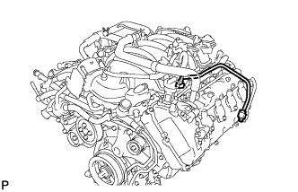
CONNECT NO. 2 FUEL TUBE
-
Connect the No. 2 fuel tube to the fuel pressure regulator Click here.
-
-
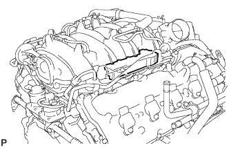
INSTALL NO. 1 FUEL HOSE
-
Install the fuel hose Click here.
-
-
INSTALL NO. 3 ENGINE COVER
-
Install the No. 3 engine cover.
-
-
INSTALL NO. 1 ENGINE COVER SUB-ASSEMBLY
-
Install the No. 1 engine cover sub-assembly.
-
-
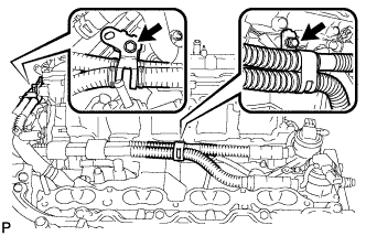
INSTALL ENGINE WIRE
-
Install the engine wire.
-
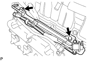
Engine Rear Side:
-
Install the 3 bolts as shown in the illustration.
- Torque:
- 8.5 N*m { 87 kgf*cm, 75 in.*lbf }
-
for RHD:
Connect the 4 clamps.
-
for LHD:
Connect the 5 clamps.
-
Connect the sensor wire connector.
-
w/ Secondary Air Injection System:
Connect the 2 air switching valve connectors.
-
-
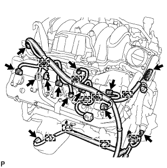
Engine RH Side:
-
Connect the 9 clamps.
-
Connect the oil level sensor connector.
-
Connect the oil pressure sender gauge connector.
-
Connect the throttle sensor connector.
-
Connect the noise filter connector.
-
Connect the fuel injector connector.
-
Connect the 2 VVT sensor connectors.
Tech Tips
The wire harnesses on the exhaust side are wrapped with white tape.
-
Connect the 4 ignition coil connectors.
-
Connect the 2 camshaft timing control valve connectors.
Tech Tips
The wire harnesses on the exhaust side are wrapped with white tape.
-
-
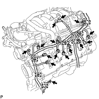
Engine LH Side:
-
Connect the 7 clamps and install the engine wire with the bolt.
- Torque:
- 20 N*m { 204 kgf*cm, 15 ft.*lbf }
-
Connect the noise filter connector.
-
Connect the fuel injector connector.
-
Connect the engine coolant temperature sensor connector.
-
Connect the purge VSV connector.
-
Connect the vacuum switching valve connector (for ACIS).
-
Connect the camshaft position sensor connector.
-
Connect the 2 VVT sensor connectors.
Tech Tips
The wire harnesses on the exhaust side are wrapped with white tape.
-
Connect the 4 ignition coil connectors.
-
Connect the 2 camshaft timing control valve connectors.
Tech Tips
The wire harnesses on the exhaust side are wrapped with white tape.
-
-