ENGINE UNIT REMOVAL

-
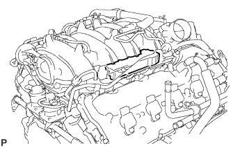
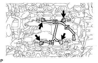
REMOVE ENGINE WIRE
-
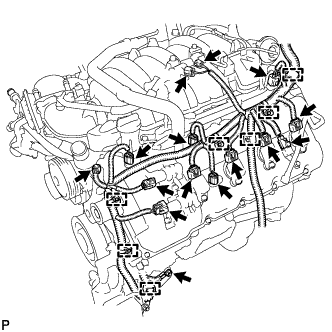
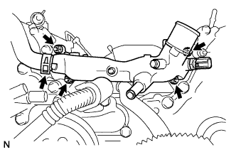
Engine LH Side:
-
Disconnect the 2 camshaft timing control valve connectors.
-
Disconnect the 4 ignition coil connectors.
-
Disconnect the 2 VVT sensor connectors.
-
Disconnect the camshaft position sensor connector.
-
Disconnect the vacuum switching valve connector (for ACIS).
-
Disconnect the purge VSV connector.
-
Disconnect the engine coolant temperature sensor connector.
-
Disconnect the fuel injector connector.
-
Disconnect the noise filter connector.
-
Remove the bolt and disconnect the 7 clamps.
-
-
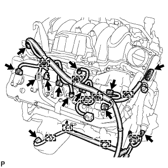
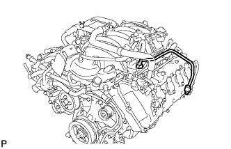
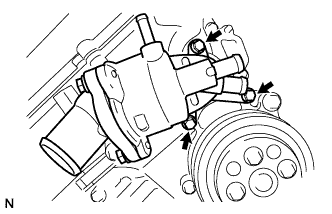
Engine RH Side:
-
Disconnect the 2 camshaft timing control valve connectors.
-
Disconnect the 4 ignition coil connectors.
-
Disconnect the 2 VVT sensor connectors.
-
Disconnect the fuel injector connector.
-
Disconnect the noise filter connector.
-
Disconnect the throttle sensor connector.
-
Disconnect the oil pressure sender gauge connector.
-
Disconnect the oil level sensor connector.
-
Disconnect the 9 clamps.
-
-
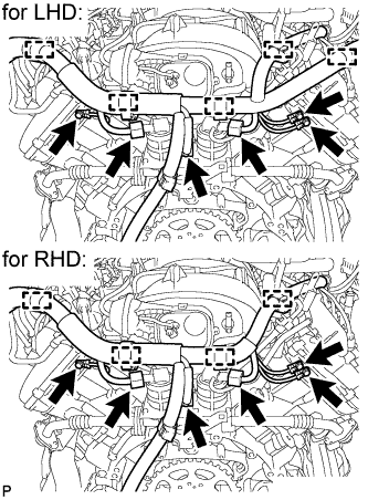
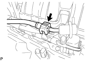
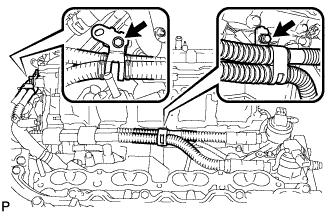
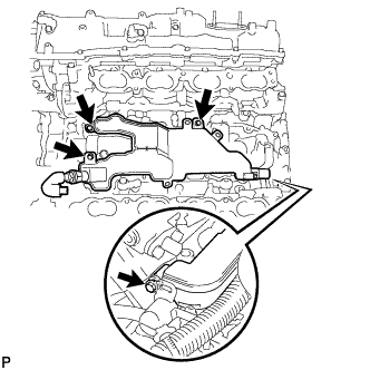
Engine Rear Side:
-
w/ Secondary Air Injection System:
Disconnect the 2 air switching valve connectors.
-
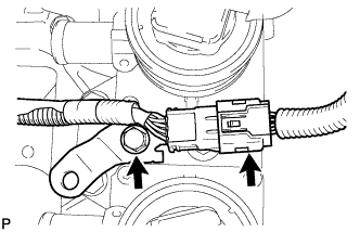
Disconnect the sensor wire connector.
-
for LHD:
Disconnect the 5 clamps.
-
for RHD:
Disconnect the 4 clamps.
-
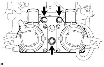
Remove the 3 bolts.
-
-
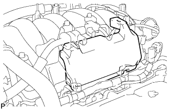
Remove the engine wire.
-
-
REMOVE NO. 1 ENGINE COVER SUB-ASSEMBLY
-
Remove the No. 1 engine cover sub-assembly.
-
-
REMOVE NO. 3 ENGINE COVER
-
Remove the No. 3 engine cover.
-
-
REMOVE NO. 1 FUEL HOSE
-
Remove the fuel hose Click here.
-
-
DISCONNECT NO. 2 FUEL TUBE
-
Disconnect the No. 2 fuel tube from the fuel pressure regulator Click here.
-
-
DISCONNECT NO. 1 FUEL TUBE
-
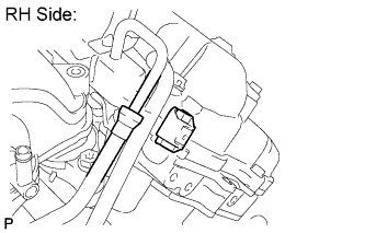
RH Side:
Disconnect the No. 1 fuel tube from the fuel delivery pipe RH (for metallic type) Click here.
- SST
- 09268-21011
-
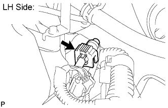
LH Side:
Disconnect the No. 1 fuel tube from the fuel delivery pipe LH Click here.
-
-
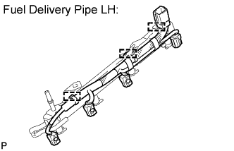
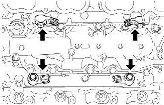
REMOVE FUEL DELIVERY PIPE SUB-ASSEMBLY LH
-
Disconnect the No. 7 wire harness connector.
-
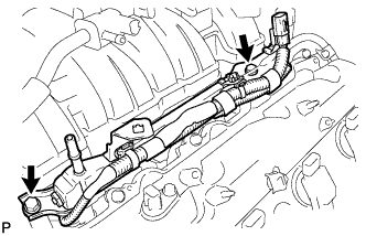
Remove the 2 bolts and fuel delivery pipe LH.
Note
When removing the delivery pipe, hold the pipe by both ends and pull it straight upward.
-
Remove the 2 delivery pipe spacers and 4 insulators from the cylinder head LH.
-
-
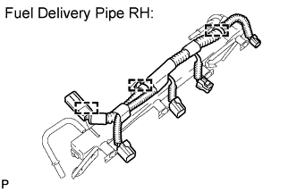
REMOVE FUEL DELIVERY PIPE SUB-ASSEMBLY RH
-
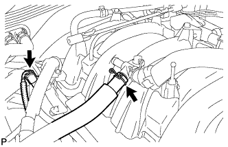
Disconnect the ventilation hose and No. 6 wire harness connector.
-
Remove the 2 bolts and fuel delivery pipe RH.
Note
When removing the delivery pipe, hold the pipe by both ends and pull it straight upward.
-
Remove the 2 delivery pipe spacers and 4 insulators from the cylinder head RH.
-
-
REMOVE FUEL INJECTOR ASSEMBLY
-
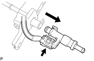
Remove the fuel injector from the fuel delivery pipe, and then disconnect the injector connector.
Note
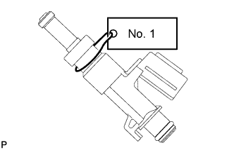
For reinstallation, attach a tag or label to the injector shaft.
-
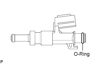
Remove the O-ring from the fuel injector.
-
Detach the 3 clamps and then remove the No. 6 wire harness from the delivery pipe RH.
-
Detach the 3 clamps and then remove the No. 7 wire harness from the delivery pipe LH.
-
-
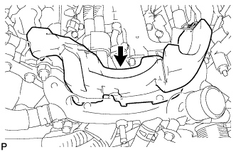
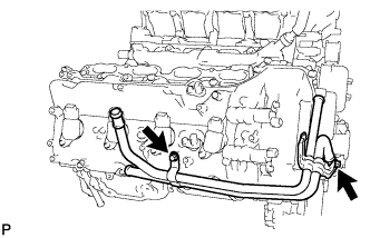
REMOVE INTAKE MANIFOLD
-
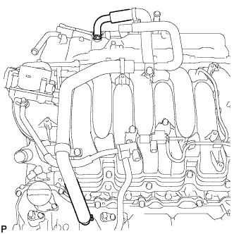
Disconnect the ventilation hose from the ventilation pipe of the cylinder head cover LH and RH.
-
Disconnect the 2 water by-pass hoses.
-
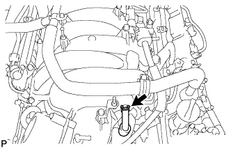
Disconnect the No. 1 ventilation hose.
-
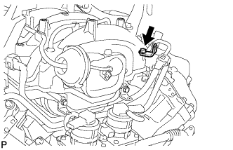
Remove the bolt and wire bracket from the intake manifold.
-
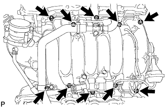
Remove the 2 nuts, 8 bolts, intake manifold and 2 gaskets.
-
-
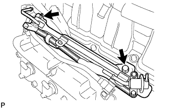
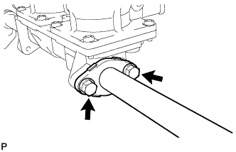
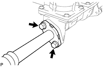
REMOVE NO. 2 FUEL TUBE
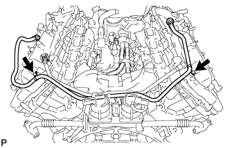
-
Remove the 2 bolts and No. 2 fuel tube.
-
-
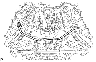
REMOVE NO. 1 FUEL TUBE
-
REMOVE NO. 2 ENGINE COVER
-
REMOVE NO. 1 ENGINE COVER
-
REMOVE NO. 2 WATER BY-PASS PIPE SUB-ASSEMBLY (w/ Oil Cooler)
-
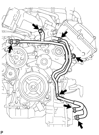
Remove the 3 bolts.
-
Disconnect the 4 hoses and remove the water by-pass pipe.
-
-
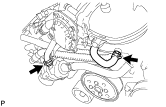
REMOVE NO. 1 WATER BY-PASS HOSE
-
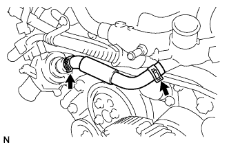
Remove the No. 1 water by-pass hose by disconnecting the hose from the water inlet housing and front water by-pass joint.
-
-
REMOVE FRONT WATER BY-PASS JOINT
-
Disconnect the No. 2 water by-pass hose from the water by-pass joint.
-
Remove the 4 nuts, water by-pass joint and 2 gaskets.
-
-
REMOVE AIR PIPE SUB-ASSEMBLY (w/ Secondary Air Injection System)
-
Remove the 2 bolts, air pipe and 2 No. 1 air hoses.
-
-
REMOVE WATER INLET HOUSING
-
Remove the 3 bolts, water inlet housing and gasket.
-
-
REMOVE WATER BY-PASS PIPE SUB-ASSEMBLY
-
Remove the 2 bolts and water by-pass pipe.
-
-
REMOVE AIR SWITCHING VALVE ASSEMBLY (w/ Secondary Air Injection System)
-
Disconnect the knock sensor connector.
-
Remove the bolt and bracket.
-
Disconnect the 2 air switching valve connectors.
-
Remove the 3 bolts and air switching valve.
-
-
REMOVE NO. 2 AIR TUBE (w/ Secondary Air Injection System)
-
Remove the 2 bolts, No. 2 air tube and gasket.
Note
Be careful not to damage the installation surface of the gaskets.
-
-
REMOVE NO. 3 AIR TUBE (w/ Secondary Air Injection System)
-
Remove the 2 bolts, No. 3 air tube and gasket.
Note
Be careful not to damage the installation surface of the gaskets.
-
-
REMOVE SENSOR WIRE
-
Disconnect the 4 knock sensor connectors.
-
Disconnect the 3 clamps. Then remove the sensor wire.
-
-
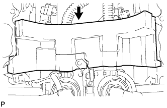
REMOVE SEPARATOR CASE
-
Remove the 4 bolts and separator case.
-
-
REMOVE KNOCK SENSOR
-
Remove the 4 bolts and 4 knock sensors.
-
-
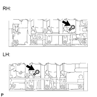
REMOVE CYLINDER BLOCK WATER DRAIN COCK SUB-ASSEMBLY
-
Remove the 2 water drain cock plugs from the water drain cocks.
-
Remove the 2 water drain cocks from the cylinder block.
-
-
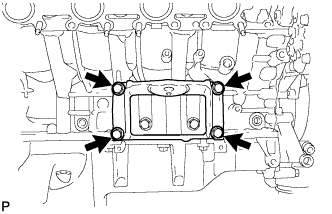
REMOVE FRONT NO. 1 ENGINE MOUNTING BRACKET RH
-
Remove the 4 bolts and mounting bracket.
-
-
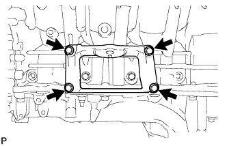
REMOVE FRONT NO. 1 ENGINE MOUNTING BRACKET LH
-
Remove the 4 bolts and mounting bracket.
-
-
REMOVE IGNITION COIL ASSEMBLY
-
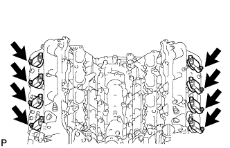
Remove the 8 bolts and 8 ignition coils.
-
-
REMOVE NOISE FILTER
-
LH:
Remove the bolt and noise filter from the cylinder head cover.
-
RH:
Remove the bolt and noise filter from the cylinder head cover.
-