ENGINE ASSEMBLY INSTALLATION

-
INSTALL FRONT NO. 2 ENGINE MOUNTING BRACKET LH
-
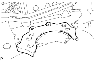
Install the engine mounting bracket LH with the bolt.
- Torque:
- 32 N*m { 326 kgf*cm, 24 ft.*lbf }
-
-
INSTALL FRONT ENGINE MOUNTING INSULATOR RH
-
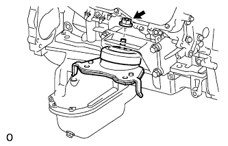
Install the mounting insulator with the nut.
- Torque:
- 72 N*m { 734 kgf*cm, 53 ft.*lbf }
-
-
INSTALL FRONT ENGINE MOUNTING INSULATOR LH
-
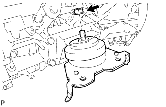
Install the mounting insulator with the nut.
- Torque:
- 72 N*m { 734 kgf*cm, 53 ft.*lbf }
-
-
REMOVE ENGINE STAND
-
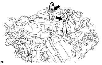
Install 2 engine hangers with 2 bolts as shown in the illustration.
- Torque:
- 43 N*m { 438 kgf*cm, 32 ft.*lbf }
Tech Tips
Item Part No. Engine hanger 12281-38150 Bolt 90119-14120 -
Attach an engine sling device and hang the engine with a chain block.
-
Remove the bolts and engine assembly from the engine stand.
Note
-
With the exception of installing the engine assembly to an engine stand or removing the engine assembly from an engine stand, do not perform any work on the engine while it is suspended, as doing so is dangerous.
-
Pay attention to the angle of the sling device as the engine assembly or engine hangers may be damaged or deformed if the angle is incorrect.
-
-
-
INSTALL ENGINE ASSEMBLY
-
Slowly lower the engine assembly into the engine compartment.
Note
Make sure that the engine is clear of all wiring and hoses.
-
Attach the engine mounting insulators to the vehicle.
-
Install the 4 engine mounting insulator bolts.
- Torque:
- 79 N*m { 806 kgf*cm, 58 ft.*lbf }
-
Remove the 2 bolts and 2 engine hangers.
-
-
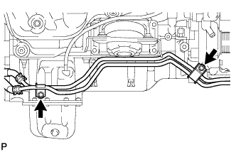
INSTALL NO. 2 WATER BY-PASS PIPE (w/o Air Cooled Transmission Oil Cooler)
-
Connect the hose and install the water by-pass pipe with the 2 bolts.
- Torque:
- 18 N*m { 184 kgf*cm, 13 ft.*lbf }
-
-
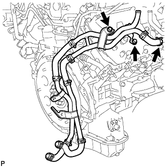
INSTALL WATER PIPE AND HOSE SUB-ASSEMBLY (w/ Air Cooled Transmission Oil Cooler)
-
Connect the hose and install the water pipe and hose with the 2 bolts.
- Torque:
- 18 N*m { 184 kgf*cm, 13 ft.*lbf }
-
-
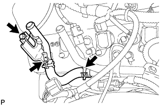
CONNECT OIL COOLER PIPE ASSEMBLY
-
Connect the oil cooler pipe with the 2 bolts.
- Torque:
- 14 N*m { 143 kgf*cm, 10 ft.*lbf }
-
-
INSTALL DRIVE PLATE AND RING GEAR SUB-ASSEMBLY
-
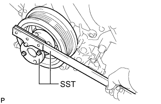
Using SST, hold the crankshaft.
- SST
- 09213-70011
- 09330-00021
-
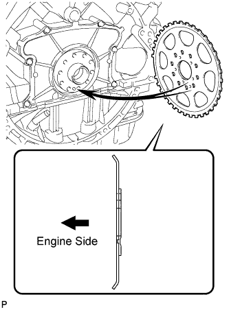
Install the crankshaft angle sensor rotor.
Tech Tips
-
Align the pin hole of the crankshaft angle sensor rotor with the pin of the crankshaft.
-
As the crankshaft angle sensor rotor is not reversible, be sure to install it so that it is facing in the direction shown in the illustration.
-
-
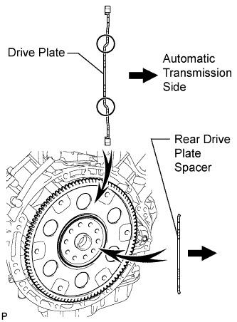
Install the drive plate and rear drive plate spacer onto the crankshaft.
Tech Tips
As the rear drive plate spacer and the drive plate are not reversible, be sure to install them so that they are facing in the direction shown in the illustration.
-
Install the drive plate and ring gear and bolts.
Tech Tips
The bolts are tightened in 2 progressive steps.
-
Clean the bolts and bolt holes.
-
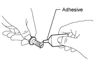
Apply adhesive to 2 or 3 threads at the end of each of the 10 bolts.
Adhesive Toyota Genuine Adhesive 1324, Three Bond 1324 or equivalent -
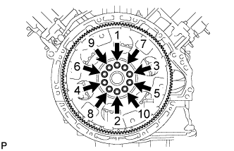
Step 1:
Install and uniformly tighten 10 new bolts in the sequence shown in the illustration.
- Torque:
- 30 N*m { 301 kgf*cm, 22 ft.*lbf }
Note
-
Do not reuse the flywheel installation bolts.
-
Do not strike or damage the flywheel installation bolts. Be sure to handle them carefully.
-
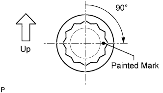
Mark the upside of each flywheel installation bolt with paint.
-
Step 2:
Tighten the flywheel installation bolts 90° as shown in the illustration.
-
Check that the painted marks are now at a 90° angle to the upside.
Note
Do not start the engine for at least an hour after installing the drive plate.
-
-
-
INSTALL REAR NO. 1 ENGINE MOUNTING INSULATOR
-
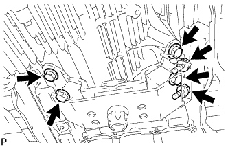
Install the rear engine mounting insulator to the transmission with the 4 bolts.
- Torque:
- 59 N*m { 602 kgf*cm, 44 ft.*lbf }
-
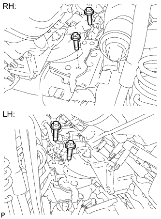
Install the front engine mounting insulator RH with the 2 bolts.
- Torque:
- 12 N*m { 122 kgf*cm, 9 ft.*lbf }
-
-
INSTALL AUTOMATIC TRANSMISSION ASSEMBLY
-
INSTALL STARTER ASSEMBLY
-
Install the flywheel housing side cover.
-
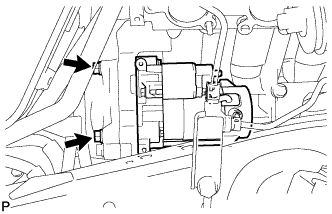
Install the starter with the 2 bolts.
- Torque:
- 37 N*m { 377 kgf*cm, 27 ft.*lbf }
-
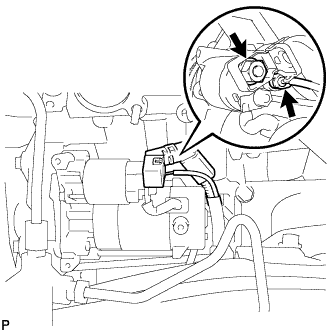
Install the starter wire with the nut.
- Torque:
- 9.8 N*m { 100 kgf*cm, 87 in.*lbf }
-
Connect the starter connector.
-
-
INSTALL STARTER COVER
-
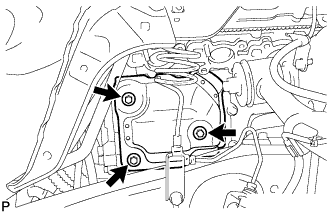
Install the starter cover with the 3 bolts.
- Torque:
- 12 N*m { 122 kgf*cm, 9 ft.*lbf }
-
-
INSTALL EXHAUST MANIFOLD SUB-ASSEMBLY RH
-
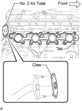
w/ Secondary Air Injection System:
-
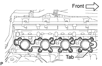
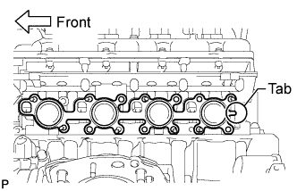
Install a new gasket to the cylinder head and a new gasket to the No. 2 air tube.
Tech Tips
-
Install the exhaust manifold gasket with the gasket tab facing toward the front of the engine.
-
Install the air tube gasket with the gasket claws facing the tube side.
-
-
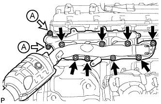
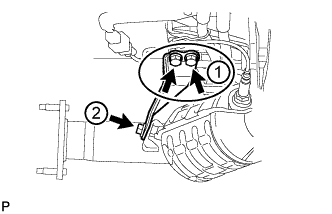
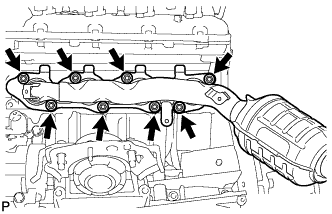
Temporarily install the exhaust manifold with the 2 nuts labeled A and 8 new nuts.
-
Uniformly tighten the nuts that are not labeled A, and then tighten the 2 nuts labeled A.
- Torque:
- for nut A
- 10 N*m { 102 kgf*cm, 7 ft.*lbf }
- except nut A
- 30 N*m { 306 kgf*cm, 22 ft.*lbf }
-
-
w/o Secondary Air Injection System:
-
Install a new gasket to the cylinder head.
Tech Tips
Install the exhaust manifold gasket with the gasket tab facing toward the front of the engine.
-
Temporarily install the exhaust manifold with the 8 new nuts.
-
Uniformly tighten the 8 nuts.
- Torque:
- 30 N*m { 306 kgf*cm, 22 ft.*lbf }
-
-
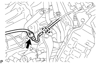
Attach the wire harness clamp to the bracket and connect the connector.
-
-
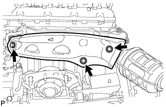
INSTALL NO. 1 EXHAUST MANIFOLD HEAT INSULATOR
-
Install the heat insulator with the 3 bolts.
- Torque:
- 10 N*m { 102 kgf*cm, 7 ft.*lbf }
-
-
INSTALL NO. 1 MANIFOLD STAY
-
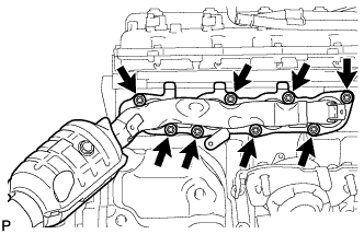
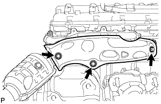
Temporarily install the manifold stay with the 3 bolts.
-
Tighten the 3 bolts in the order shown in the illustration.
- Torque:
- 40 N*m { 408 kgf*cm, 30 ft.*lbf }
-
-
INSTALL EXHAUST MANIFOLD SUB-ASSEMBLY LH
-
w/ Secondary Air Injection System:
-
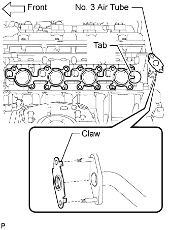
Install a new gasket to the cylinder head and a new gasket to the No. 3 air tube.
Tech Tips
-
Install the exhaust manifold gasket with the gasket tab facing toward the rear of the engine.
-
Install the air tube gasket with the gasket claws facing the tube side.
-
-
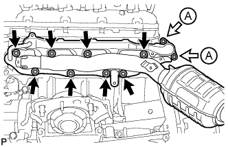
Temporarily install the exhaust manifold with the 2 nuts labeled A and 8 new nuts.
-
Uniformly tighten the nuts that are not labeled A, and then tighten the 2 nuts labeled A.
- Torque:
- for nut A
- 10 N*m { 102 kgf*cm, 7 ft.*lbf }
- except nut A
- 30 N*m { 306 kgf*cm, 22 ft.*lbf }
-
-
w/o Secondary Air Injection System:
-
Install a new gasket to the cylinder head.
Tech Tips
Install the exhaust manifold gasket with the gasket tab facing toward the front of the engine.
-
Temporarily install the exhaust manifold with the 8 new nuts.
-
Uniformly tighten the 8 nuts.
- Torque:
- 30 N*m { 306 kgf*cm, 22 ft.*lbf }
-
-
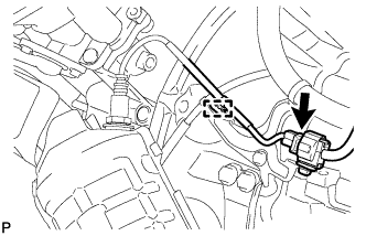
Attach the wire harness clamp to the bracket and connect the connector.
-
-
INSTALL NO. 2 EXHAUST MANIFOLD HEAT INSULATOR
-
Install the heat insulator with the 3 bolts.
- Torque:
- 10 N*m { 102 kgf*cm, 7 ft.*lbf }
-
-
INSTALL NO. 2 MANIFOLD STAY
-
Temporarily install the manifold stay with the 3 bolts.
-
Tighten the 3 bolts in the order shown in the illustration.
- Torque:
- 40 N*m { 408 kgf*cm, 30 ft.*lbf }
-
-
INSTALL PROPELLER SHAFT HEAT INSULATOR
-
Install the heat insulator with the 2 bolts.
- Torque:
- 16 N*m { 160 kgf*cm, 12 ft.*lbf }
-
-
INSTALL REAR PROPELLER SHAFT ASSEMBLY
-
INSTALL FRONT PROPELLER SHAFT ASSEMBLY
-
INSTALL FRONT EXHAUST PIPE ASSEMBLY
-
Install a new gasket and the front exhaust pipe to the exhaust manifold RH with 2 new nuts.
- Torque:
- 54 N*m { 551 kgf*cm, 40 ft.*lbf }
-
Install the wire harness clamp bracket of the oxygen sensor to the transmission with the bolt.
- Torque:
- 29 N*m { 296 kgf*cm, 21 ft.*lbf }
-
Connect the heated oxygen sensor connector.
-
-
INSTALL FRONT NO. 2 EXHAUST PIPE ASSEMBLY
-
Install a new gasket and the front No. 2 exhaust pipe to the exhaust manifold LH with 2 new nuts.
- Torque:
- 54 N*m { 551 kgf*cm, 40 ft.*lbf }
-
Install the wire harness clamp bracket of the oxygen sensor to the transmission with the bolt.
- Torque:
- 29 N*m { 296 kgf*cm, 21 ft.*lbf }
-
Connect the heated oxygen sensor connector.
-
-
INSTALL CENTER EXHAUST PIPE ASSEMBLY
-
Install 2 new gaskets to the front exhaust pipe and front No. 2 exhaust pipe.
-
Install the center exhaust pipe to the 3 exhaust pipe supports, and then install the 4 bolts.
- Torque:
- 48 N*m { 489 kgf*cm, 35 ft.*lbf }
-
-
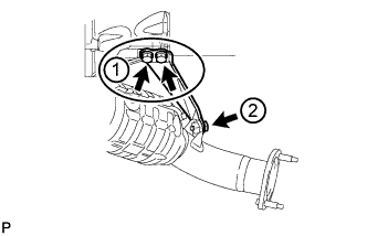
INSTALL TAILPIPE ASSEMBLY
-
Install the tailpipe to the 2 exhaust pipe supports.
-
Install a new gasket to the center exhaust pipe.
-
Connect the tailpipe to the center exhaust pipe.
-
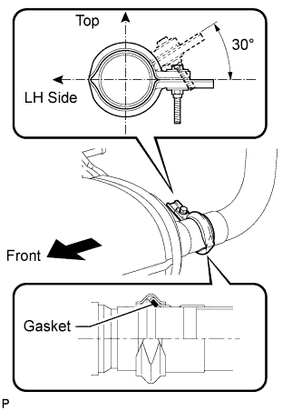
Attach a new clamp to the tailpipe and center exhaust pipe. Then install the bolt to the clamp.
- Torque:
- 32 N*m { 326 kgf*cm, 24 ft.*lbf }
Tech Tips
Install the clamp within the angle range shown in the illustration.
-
-
INSTALL ENGINE OIL LEVEL DIPSTICK GUIDE
-
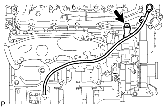
Apply a light coat of engine oil to a new O-ring.
-
Install the O-ring to the guide.
-
Install the dipstick guide with the bolt.
- Torque:
- 10 N*m { 102 kgf*cm, 7 ft.*lbf }
-
Install the dipstick.
-
-
INSTALL GENERATOR ASSEMBLY
-
for 150A Type:
-
for 180A Type:
-
-
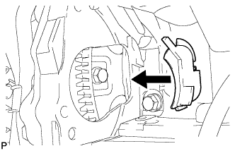
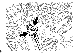
CONNECT VANE PUMP ASSEMBLY
Tech Tips
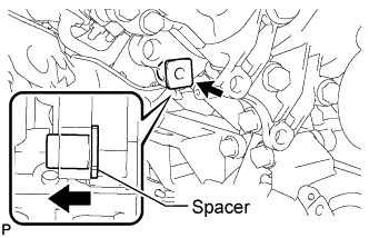
Before performing the following procedures, move the spacer until the vane pump can be installed.
-
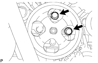
Connect the vane pump to the timing chain cover with the 2 bolts.
- Torque:
- 21 N*m { 214 kgf*cm, 15 ft.*lbf }
-
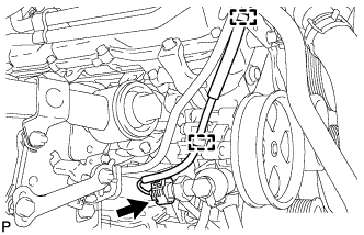
Connect the 2 clamps and power steering oil pressure switch connector.
-
-
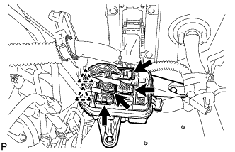
CONNECT COOLER COMPRESSOR ASSEMBLY
-
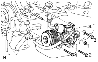
Install the cooler compressor with the stud bolt.
- Torque:
- 10 N*m { 102 kgf*cm, 7 ft.*lbf }
-
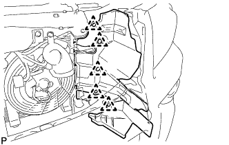
Install the 3 bolts and nut.
- Torque:
- 25 N*m { 250 kgf*cm, 18 ft.*lbf }
Note
Tighten the bolts and nut in the order shown in the illustration to install the cooler compressor.
-
-
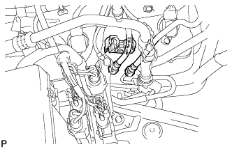
CONNECT WIRE HARNESS AND HOSE
-
Connect the clamp and 2 connectors.
-
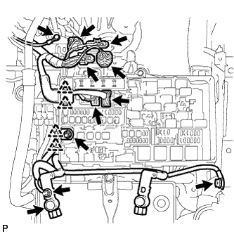
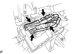
Connect the 2 connectors and 2 clips to the engine room junction block.
-
Install the engine wire with the nut. Then connect the 2 clips.
- Torque:
- 10 N*m { 102 kgf*cm, 7 ft.*lbf }
-
w/ Secondary Air Injection System:
Connect the 4 air injection control driver connectors.
-
Install the ground wire to the bracket with the bolt.
- Torque:
- 8.0 N*m { 82 kgf*cm, 71 in.*lbf }
-
Install the ground wire to the body with the bolt.
- Torque:
- 8.4 N*m { 86 kgf*cm, 74 in.*lbf }
-
Connect the cable to the positive (+) battery terminal.
-
Install the wire to the positive (+) battery cable with the nut.
- Torque:
- 5.4 N*m { 55 kgf*cm, 48 in.*lbf }
-
w/ Secondary Air Injection System:
Connect the 2 air injection system hoses.
-
Install the ground wire with the bolt.
- Torque:
- 8.0 N*m { 82 kgf*cm, 71 in.*lbf }
-
w/ Secondary Air Injection System:
Connect the 3 clamps and 2 air pump connectors.
-
w/ Secondary Air Injection System:
Install the connector bracket with the nut.
- Torque:
- 8.0 N*m { 82 kgf*cm, 71 in.*lbf }
-
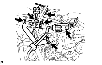
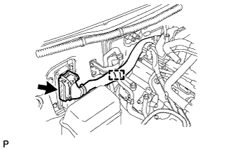
Connect the 4 connectors.
-
for RHD:
Connect the 4 connectors and 2 clips to the connector holder block.
-
for LHD:
Connect the 4 connectors and clamp to the connector holder block.
-
-
Connect the ECM connector.
-
for RHD:
Connect the 2 clamps and ECM connector.
Tech Tips
Refer to the following procedures to connect the ECM connector Click here.
-
for LHD:
Connect the clamp and ECM connector.
Tech Tips
Refer to the following procedures to connect the ECM connector Click here.
-
-
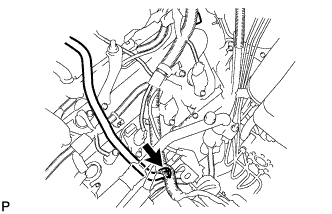
Connect the purge line hose.
-
-
CONNECT FUEL MAIN AND RETURN HOSE
-
Connect the fuel main and return hoses Click here.
-
Install the fuel pipe clamp.
-
-
INSTALL WATER HOSE SUB-ASSEMBLY
-
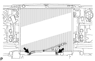
INSTALL RADIATOR ASSEMBLY
-
Set the radiator bracket hooks to the radiator support holes.
-
Install the radiator with the 4 bolts.
- Torque:
- 18 N*m { 184 kgf*cm, 13 ft.*lbf }
-
Connect the 2 oil cooler hoses.
-
-
INSTALL FAN SHROUD
-
Install the fan pulley.
-
Place the shroud together with the coupling fan between the radiator and engine.
Note
Be careful not to damage the radiator core.
-
Temporarily install the fluid coupling fan to the fluid coupling bracket with the 4 nuts. Tighten the nuts as much as possible by hand.
-
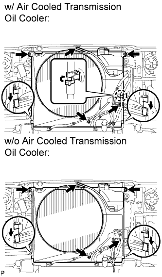
Attach the claws of the shroud to the radiator as shown in the illustration.
-
Install the shroud with the 2 bolts.
- Torque:
- 8.0 N*m { 82 kgf*cm, 71 in.*lbf }
-
Connect the oil cooler tube to the fan shroud with the 2 bolts.
- Torque:
- 5.0 N*m { 51 kgf*cm, 44 in.*lbf }
-
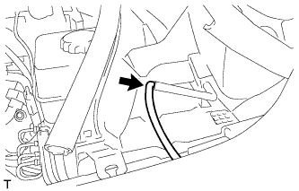
w/ Air Cooled Transmission Oil Cooler:
Pass the hose through the flexible hose clamp and close the clamp as shown in the illustration.
-
Connect the reservoir hose to the upper radiator tank.
-
Install the fan and generator V belt Click here.
-
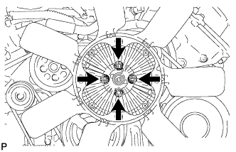
Tighten the 4 nuts of the fluid coupling fan.
- Torque:
- 21 N*m { 214 kgf*cm, 15 ft.*lbf }
-
-
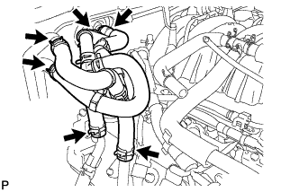
INSTALL NO. 2 RADIATOR HOSE
-
INSTALL NO. 1 RADIATOR HOSE
-
INSTALL AIR CLEANER ASSEMBLY
-
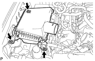
Install the air cleaner with the 3 bolts.
- Torque:
- 5.0 N*m { 51 kgf*cm, 44 in.*lbf }
-
-
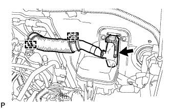
INSTALL AIR CLEANER HOSE ASSEMBLY
-
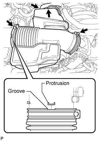
Install the air cleaner hose so that the protrusion of the air cleaner cap aligns with the groove of the hose as shown in the illustration.
-
Tighten the 2 clamps.
- Torque:
- 2.5 N*m { 25 kgf*cm, 22 in.*lbf }
-
Connect the vacuum hose.
-
Connect the No. 2 ventilation hose.
-
-
INSTALL HOOD SUB-ASSEMBLY
-
Install the hood with the 4 bolts.
- Torque:
- 13 N*m { 133 kgf*cm, 10 ft.*lbf }
-
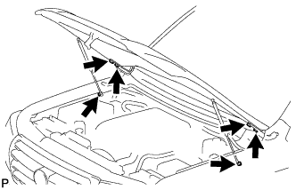
Connect the 2 hood supports with the 2 hood support bolts.
- Torque:
- 18 N*m { 184 kgf*cm, 13 ft.*lbf }
CAUTION:
Install the hood support while supporting the hood by hand.
Note
Check that the hood support is engaged in the ball joint and that it cannot be pulled out.
-
-
ADJUST HOOD SUB-ASSEMBLY
-

Adjust the hood position.
-
Loosen the 4 hinge bolts of the hood.
-
Move the hood and adjust the clearance between the hood and front fender.
-
Tighten the 4 hinge bolts of the hood after the adjustment.
- Torque:
- 13 N*m { 133 kgf*cm, 10 ft.*lbf }
-

Adjust the cushion rubber so that the height of the hood and fender are aligned.
Tech Tips
Raise or lower the front end of the hood by turning the cushion rubber.
-
-
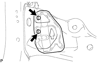
Adjust the hood lock.
-

Using a screwdriver, remove the hood lock nut cap as shown in the illustration.
Tech Tips
Tape the screwdriver tip before use.
-

Loosen the 2 bolts and hood lock nut.
-
Adjust the hood lock position so that the striker can enter it smoothly.
-
Tighten the bolts and nut after the adjustment.
- Torque:
- 5.5 N*m { 56 kgf*cm, 49 in.*lbf }
-
Install a new cap.
-
-
-
INSTALL COWL TOP VENTILATOR LOUVER SUB-ASSEMBLY
-
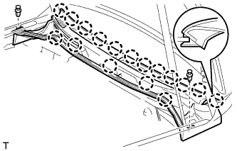
Push in the ventilator louver to attach the 17 claws and install the ventilator louver.
-
Install the 2 clips.
-
Connect the washer hose.
-
-
INSTALL HOOD TO COWL TOP SEAL
-
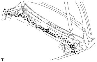
Attach the 12 clips and 4 clamps to install the hood to cowl top seal.
-
-
INSTALL FRONT FENDER MAIN SEAL LH
-

Attach the 3 clips to install the fender main seal.
-
-
INSTALL FRONT FENDER MAIN SEAL RH
Tech Tips
Use the same procedure described for the LH side.
-
INSTALL FRONT WIPER ARM LH
-
Stop the wiper motor at the automatic stop position.
-
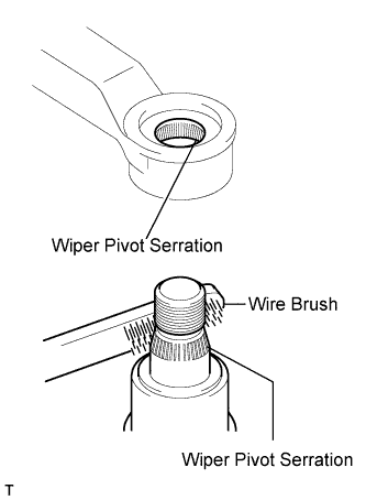
Clean the wiper pivot serrations with a wire brush.
-
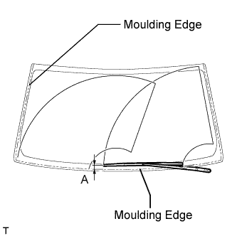
Install the wiper arm and blade with the nut. Make sure that the wiper arm and blade come to the position shown in the illustration.
Standard Position Specified Condition A 16.8 to 36.8 mm (0.661 to 1.45 in.) - Torque:
- 25 N*m { 255 kgf*cm, 18 ft.*lbf }
Tech Tips
Hold down the wiper arm hinge with your hand while tightening the nut.
-
-
INSTALL FRONT WIPER ARM RH
-
Stop the wiper motor at the automatic stop position.
-
Clean the wiper pivot serrations with a wire brush.
-
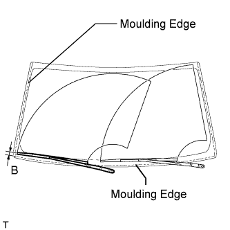
Install the wiper arm and blade with the nut. Make sure that the wiper arm and blade come to the position shown in the illustration.
Standard Position Specified Condition B 20.0 to 40.0 mm (0.787 to 1.57 in.) - Torque:
- 25 N*m { 255 kgf*cm, 18 ft.*lbf }
Tech Tips
Hold down the wiper arm hinge with your hand while tightening the nut.
-
Operate the front wipers while spraying washer fluid on the windshield glass. Make sure that the front wipers function properly and there is no interference with the vehicle body.
-
-
INSTALL RADIATOR SIDE DEFLECTOR LH
-
Install the side deflector with the 5 clips.
-
-
INSTALL RADIATOR SIDE DEFLECTOR RH (w/o Air Cooled Transmission Oil Cooler)
-
Install the side deflector with the 5 clips.
-
-
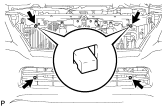
INSTALL RADIATOR GRILLE
-
w/ Wide View Front Monitor System:
Connect the connector.
-
Attach the 14 claws to install the radiator grille assembly.
-
Attach the 4 clips to install the detached part of the upper radiator seal.
-
Install the screw and 2 clips.
-
-
INSTALL FRONT FENDER APRON SEAL REAR RH
-
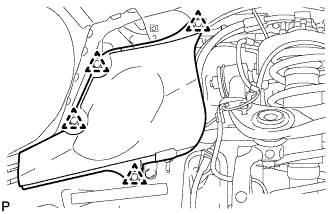
Install the fender apron seal with the 4 clips.
-
-
INSTALL FRONT FENDER APRON SEAL FRONT RH
-
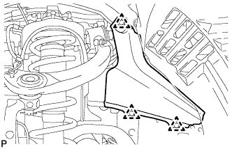
Install the fender apron seal with the 3 clips.
-
-
INSTALL FRONT FENDER APRON SEAL REAR LH
-
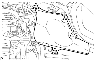
Install the fender apron seal with the 4 clips.
-
-
INSTALL FRONT FENDER APRON SEAL FRONT LH
-
Install the fender apron seal with the 4 clips.
-
-
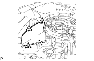
INSTALL OIL PAN PROTECTOR ASSEMBLY
-
Install the oil pan protector with the 4 bolts.
- Torque:
- 63 N*m { 642 kgf*cm, 46 ft.*lbf }
-
-
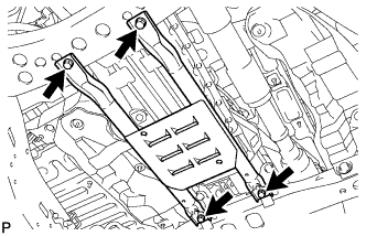
INSTALL NO. 2 ENGINE UNDER COVER
-
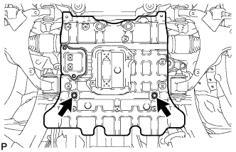
Install the No. 2 engine under cover with the 2 bolts.
- Torque:
- 29 N*m { 296 kgf*cm, 21 ft.*lbf }
-
-
INSTALL NO. 1 ENGINE UNDER COVER SUB-ASSEMBLY
-
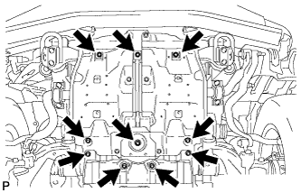
Install the No. 1 engine under cover with the 10 bolts.
- Torque:
- 29 N*m { 296 kgf*cm, 21 ft.*lbf }
-
-
INSTALL FRONT FENDER SPLASH SHIELD SUB-ASSEMBLY LH
-
Push in the clip to install the front fender splash shield sub-assembly LH.
-
Install the 3 bolts and 2 screws.
-
-
INSTALL FRONT FENDER SPLASH SHIELD SUB-ASSEMBLY RH
Tech Tips
Use the same procedure described for the LH side.
-
ADD ENGINE OIL
-
Add fresh oil and install the oil filler cap.
Standard Oil Grade Oil Grade Oil Viscosity (SAE) API grade SL "Energy-Conserving", SM "Energy-Conserving", SN "Resource-Conserving" or ILSAC multigrade engine oil
API grade SL, SM or SN multigrade engine oil
0W-20
5W-20
5W-30
10W-30
15W-40
20W-50
Standard Oil Capacity Item Specified Condition Drain and refill with oil filter change 7.5 liters (7.9 US qts, 6.6 Imp. qts) Drain and refill without oil filter change 7.1 liters (7.5 US qts, 6.2 Imp. qts) Dry fill 9.3 liters (9.8 US qts, 8.2 Imp. qts)
-
-
ADD ENGINE COOLANT
-
Add engine coolant.
Standard Capacity Item Specified Condition with transmission oil cooler 16.7 liters (17.6 US qts, 14.7 Imp. qts) without transmission oil cooler 16.2 liters (17.1 US qts, 14.3 Imp. qts) Note
Do not substitute plain water for engine coolant.
Tech Tips
TOYOTA vehicles are filled with TOYOTA SLLC at the factory. In order to avoid damage to the engine cooling system and other technical problems, only use TOYOTA SLLC or similar high quality ethylene glycol based non-silicate, non-amine, non-nitrite, non-borate coolant with long-life hybrid organic acid technology (coolant with long-life hybrid organic acid technology consists of a combination of low phosphates and organic acids).
-
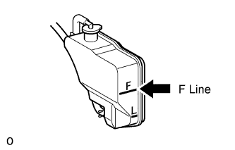
Slowly pour coolant into the radiator reservoir until it reaches the F line.
-
Install the reservoir cap.
-
Press the No. 1 and No. 2 radiator hoses several times by hand, and then check the coolant level. If the coolant level is low, add coolant.
-
Install the radiator cap.
-
Start the engine and warm it up until the thermostat opens.
Note
Switch off the A/C.
-
Maintain the engine speed at 2000 to 2500 rpm.
Note
-
Make sure that the radiator reservoir still has some coolant in it.
-
Pay attention to the needle of the water temperature meter. Make sure that the needle does not show an abnormally high temperature.
-
If there is not enough coolant, the engine may burn out or overheat.
-
Immediately after starting the engine, if the radiator reservoir does not have any coolant, perform the following: 1) stop the engine, 2) wait until the coolant has cooled down, and 3) add coolant until the coolant is filled to the F line.
-
Run the engine at 2000 rpm until the coolant level has stabilized.
-
-
Press the No. 1 and No. 2 radiator hoses several times by hand to bleed air.
CAUTION:
-
Wear protective gloves.
-
Be careful as the radiator hoses are hot.
-
Keep your hands away from the fan.
-
-
Stop the engine, and wait until the engine coolant cools down to ambient temperature.
CAUTION:
Do not remove the radiator cap while the engine and radiator are still hot. Pressurized, hot engine coolant and steam may be released and cause serious burns.
-
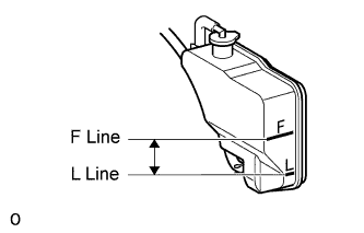
Check that the coolant level is between the F and L lines.
If the coolant level is below the L line, repeat all of the procedures above.
If the coolant level is above the F line, drain coolant so that the coolant level is between the F and L lines.
-
-
CONNECT CABLE TO NEGATIVE BATTERY TERMINAL
Note
When disconnecting the cable, some systems need to be initialized after the cable from the cable is reconnected Click here.
-
INSPECT FOR OIL LEAK
-
Start the engine. Make sure that there are no oil leaks from the area that was worked on.
-
-
INSPECT FOR COOLANT LEAK
-
Fill the radiator with coolant and attach a radiator cap tester.
-
Warm up the engine.
-
Using the radiator cap tester, increase the pressure inside the radiator to 123 kPa (1.3 kgf/cm2, 18 psi), and check that the pressure does not drop.
If the pressure drops, check the hoses, radiator and water pump for leaks. If no external leaks are found, check the heater core, cylinder block and head.
-
-
INSPECT FOR EXHAUST GAS LEAK
-
INSPECT FOR FUEL LEAK
-
Connect the intelligent tester to the DLC3.
-
Turn the engine switch on (IG) and intelligent tester on.
Note
Do not start the engine.
-
Enter the following menus: Powertrain / Engine and ECT / Active Test / Control the Fuel Pump Speed Control.
-
Check that there are no fuel leaks after doing maintenance anywhere on the fuel system.
-
-
INSPECT SHIFT LEVER POSITION
-
When moving the shift lever from P to R with the engine switch on (IG) and the brake pedal depressed, make sure that it moves smoothly and correctly into position.
-
Check that the shift lever does not stop when moving the shift lever from R to P, and check that the shift lever does not stick when moving the shift lever from D to S.
-
Start the engine and make sure that the vehicle moves forward after moving the shift lever from N to D and moves rearward after moving the shift lever to R.
If the operation cannot be performed as specified, inspect the park/neutral position switch assembly and check the shift lever assembly installation condition.
-
-
INSPECT IGNITION TIMING
-
Warm up and stop the engine.
-
Allow the engine to warm up to a normal operating temperature.
-
-
Remove the engine room side cover LH.
-
Remove the engine room side cover RH.
-
Remove the upper radiator support seal.
-
Remove the V-bank cover.
-
When using the intelligent tester:
-
Connect the intelligent tester to the DLC3.
-
Start the engine and idle it.
-
Turn the intelligent tester ON.
-
Enter the following menus: Powertrain / Engine and ECT / Data List / Primary / IGN Advance.
Tech Tips
Refer to the intelligent tester operator's manual for further details.
Standard ignition timing 8 to 12° BTDC @ idle (transmission in neutral and A/C switch off) -
Disconnect the intelligent tester from the DLC3.
-
-
When not using the intelligent tester:
-
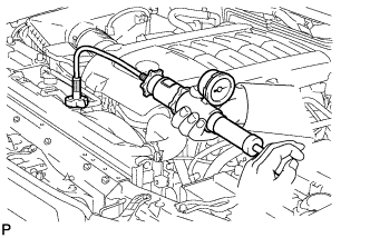
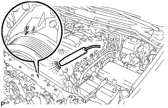
Connect the tester probe of a timing light to the wire of the ignition coil connector for the No. 1 cylinder.
Note
Use a timing light that detects primary signals.
-
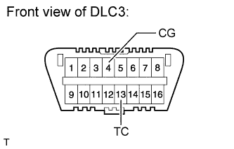
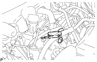
Using SST, connect terminals 13 (TC) and 4 (CG) of the DLC3.
- SST
- 09843-18040
Note
-
Confirm the terminal numbers before connecting them. Connecting the wrong terminals can damage the engine.
-
Switch off all accessories and the A/C before connecting the terminals.
-
Using the timing light, check the ignition timing.
Standard ignition timing 8 to 12° BTDC @ idle (transmission in neutral and A/C switch off) -
Remove SST from the DLC3.
-
Check the ignition timing.
Standard ignition timing 7 to 24° BTDC @ idle (transmission in neutral and A/C switch off) -
Disconnect the timing light from the engine.
-
-
Install the V-bank cover.
-
Install the upper radiator support seal.
-
Install the engine room side cover RH.
-
Install the engine room side cover LH.
-
-
INSPECT ENGINE IDLE SPEED
-
Warm up and stop the engine.
-
Allow the engine to warm up to a normal operating temperature.
-
-
When using the intelligent tester:
-
Connect the intelligent tester to the DLC3.
Note
Switch off all accessories and the A/C before connecting the intelligent tester.
-
Race the engine at 2500 rpm for approximately 90 seconds.
-
Turn the intelligent tester ON.
-
Enter the following menus: Powertrain / Engine and ECT / Data List / Primary / Engine Speed.
Standard idle speed 650 to 750 rpm (transmission in neutral and A/C switch off) Tech Tips
Refer to the intelligent tester operator's manual for further details.
If the idle speed is not as specified, check the air intake system.
-
Disconnect the intelligent tester from the DLC3.
-
-
When not using the intelligent tester:
-
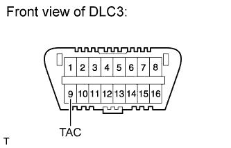
Using SST, connect the tachometer probe to terminal 9 (TAC) of the DLC3.
- SST
- 09843-18030
Note
-
Confirm the terminal number before connecting the probe. Connecting the probe to the wrong terminal can damage the engine.
-
Switch off all accessories and the A/C before connecting the probe.
-
Race the engine at 2500 rpm for approximately 90 seconds.
-
Check the idle speed.
Standard idle speed 650 to 750 rpm (transmission in neutral and A/C switch off) If the idle speed is not as specified, check the air intake system.
-
Disconnect the tachometer probe from the DLC3.
-
-
-
INSPECT CO/HC
Tech Tips
This check is used only to determine whether or not the idle CO/HC complies with regulations.
-
Start the engine.
-
Keep the engine speed at 2500 rpm for approximately 180 seconds.
-
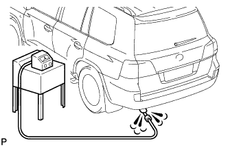
Insert the CO/HC meter testing probe at least 40 cm (1.31 ft.) into the tailpipe during idling.
-
Immediately check CO/HC concentration at idle and/or 2500 rpm.
Tech Tips
When performing the 2 mode (2500 rpm and idle) test, follow the measurement order prescribed by the applicable local regulations.
-
If the CO/HC concentration does not comply with the regulations, troubleshoot in the order given below.
-
Check the A/F sensor operation Click here and heated oxygen sensor operation Click here.
-
See the table below for possible causes, and then inspect and correct the applicable causes if necessary.
CO HC Symptom Cause Normal High Rough idle
-
Faulty ignitions:
-
Incorrect timing
-
Plugs (contaminated, shorted or gaps are defective)
-
Incorrect valve clearance
-
Leaky intake and exhaust valves
-
Leaky cylinder
Low High Rough idle
(Fluctuating HC reading)
-
Vacuum leaks:
-
PCV hose
-
Intake manifold
-
Throttle body
-
Lean mixture causing misfire
High High Rough idle
(Black smoke from exhaust)
-
Restricted air filter
-
Faulty SFI system:
-
Faulty pressure regulator
-
Defective ECT sensor
-
Faulty ECM
-
Faulty injectors
-
Faulty throttle position sensor
-
Faulty MAF meter
-
-
-
-
INSPECT ENGINE OIL LEVEL
-
Warm up the engine. Then stop the engine and wait for 5 minutes.
-
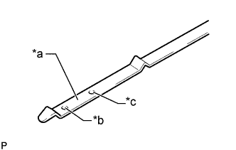
Text in Illustration *a Measuring Surface *b Low Level Mark *c Full Level Mark Check that the engine oil level is between the dipstick low level mark and full level mark.
If the level is low, check for leakage and add oil up to the full level mark.
Note
Do not fill engine oil above the full level mark.
Tech Tips
A certain amount of engine oil will be consumed while driving. In the following situations, oil consumption may increase, and engine oil may need to be refilled in between oil maintenance intervals.
-
When the engine is new, for example directly after purchasing the vehicle or after replacing the engine.
-
If low quality oil or oil of an inappropriate viscosity is used.
-
When driving at high engine speed or with a heavy load, (when towing, or), when driving while accelerating or decelerating frequently.
-
When leaving the idling for a long time, or when driving frequently through heavy traffic.
When judging the amount of oil consumption, keep in mind that the oil may have become diluted, making it difficult to judge the true level accurately.
-
-
-
INSPECT ENGINE COOLANT LEVEL
-
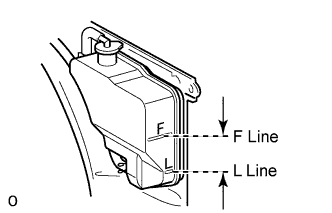
Check that the engine coolant level is between the L and F lines when the engine is cold.
If the engine coolant is below the L line, check for leaks and add "TOYOTA Super Long Life Coolant" or similar high quality ethylene glycol based non-silicate, non-amine, non-nitrite and non-borate coolant with long-life hybrid organic acid technology to the F line.
Note
Do not substitute plain water for engine coolant.
-
Remove the radiator cap, and check that the coolant level is up to the radiator filler hole.
-
-
INSTALL V-BANK COVER SUB-ASSEMBLY
-
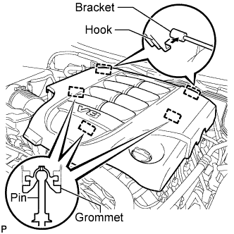
Attach the 2 V-bank cover hooks to the bracket. Then align the 3 V-bank cover grommets with the 3 pins, and press down on the V-bank cover to attach the pins.
-
-
INSTALL UPPER RADIATOR SUPPORT SEAL
-
Install the upper radiator support seal with the 3 clips.
-
-
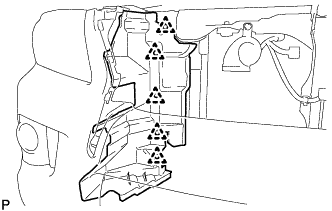
INSTALL ENGINE ROOM SIDE COVER RH
-
Install the engine room side cover RH with the 7 clips.
-
-
INSTALL ENGINE ROOM SIDE COVER LH
-
Install the engine room side cover LH with the 7 clips.
-