CYLINDER HEAD GASKET INSTALLATION

-
INSPECT CYLINDER HEAD SET BOLT
-
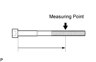
Using a vernier caliper, measure the diameter of the elongated thread at the measuring point.
Measuring point 94 mm (3.70 in.) for intake side bolt 89 mm (3.50 in.) for exhaust side bolt Standard diameter 10.85 to 11.00 mm (0.427 to 0.433 in.) Minimum diameter 10.6 mm (0.417 in.) If the diameter is less than the minimum, replace the cylinder head bolt.
Tech Tips
If a visual check reveals no excessively thin areas, check the center of the bolt (see illustration) and find the area that has the smallest diameter.
-
-
INSPECT CYLINDER HEAD SUB-ASSEMBLY
-
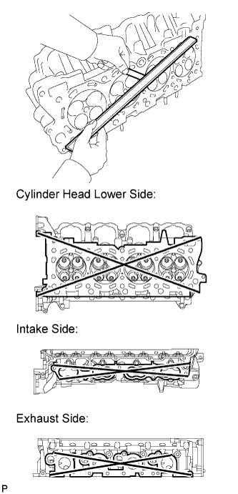
Using a precision straightedge and feeler gauge, measure the warpage of the surfaces where the cylinder head contacts the cylinder block and manifold.
Standard Warpage Item Specified Condition Cylinder head lower side 0.05 mm (0.00197 in.) Intake side 0.08 mm (0.00315 in.) Exhaust side 0.05 mm (0.00197 in.) Maximum warpage 0.10 mm (0.00394 in.) If the warpage is more than the maximum, replace the cylinder head.
-
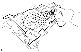
Using a dye penetrant, check the intake ports, exhaust ports and cylinder surface for cracks.
If cracked, replace the cylinder head.
-
-
INSTALL CYLINDER HEAD SUB-ASSEMBLY RH
-
Clean the cylinder block with solvent.
-
Set the piston of the No. 1 cylinder to slightly ATDC.
-
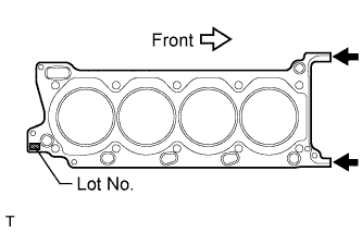
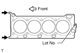
Place the cylinder head gasket on the cylinder block surface with the front face of the Lot No. stamp upward.
Note
-
Be careful of the installation direction.
-
Make sure that no oil is on the front end (indicated by the arrows) of the cylinder head gasket.
-
-
Place the cylinder head on the cylinder block.
Tech Tips
The cylinder head bolts are tightened in 3 progressive steps.
Note
-
Ensure that no oil is on the mounting surface of the cylinder head.
-
Gently place the cylinder head in order not to damage the gasket with the bottom part of the head.
-
-
Apply a light coat of engine oil to the threads and under the heads of the cylinder head bolts.
-
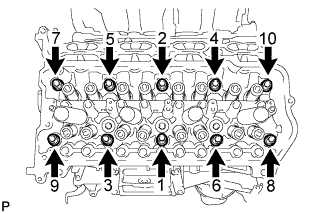
Step 1:
-
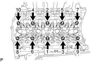
Using a 10 mm bi-hexagon wrench, install and uniformly tighten the 10 cylinder head bolts with the plate washers in several steps in the sequence shown in the illustration.
- Torque:
- 36 N*m { 367 kgf*cm, 27 ft.*lbf }
-
-
Step 2:
-
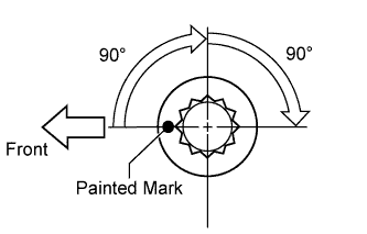
Mark each cylinder head bolt head with paint as shown in the illustration.
-
Tighten the cylinder head bolts 90° in the sequence shown in step 1.
-
-
Step 3:
-
Tighten the cylinder head bolts another 90° in the sequence shown in step 1.
-
Check that the painting marks are now facing rearward.
-
-
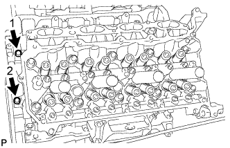
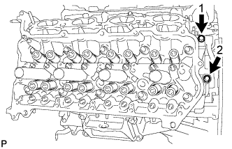
Uniformly install the 2 bolts in the sequence shown in the illustration.
- Torque:
- 21 N*m { 214 kgf*cm, 15 ft.*lbf }
-
-
INSTALL CYLINDER HEAD SUB-ASSEMBLY LH
-
Clean the cylinder block with solvent.
-
Set the piston of the No. 1 cylinder to slightly ATDC.
-
Place the cylinder head gasket on the cylinder block surface with the front face of the Lot No. stamp upward.
Note
-
Be careful of the installation direction.
-
Make sure that no oil is on the front end (indicated by the arrows) of the cylinder head gasket.
-
-
Place the cylinder head on the cylinder block.
Tech Tips
The cylinder head bolts are tightened in 3 progressive steps.
Note
-
Ensure that no oil is on the mounting surface of the cylinder head.
-
Gently place the cylinder head in order not to damage the gasket with the bottom part of the head.
-
-
Apply a light coat of engine oil to the threads and under the heads of the cylinder head bolts.
-
Step 1:
-
Using a 10 mm bi-hexagon wrench, install and uniformly tighten the 10 cylinder head bolts with the plate washers in several steps in the sequence shown in the illustration.
- Torque:
- 36 N*m { 367 kgf*cm, 27 ft.*lbf }
-
-
Step 2:
-
Mark each cylinder head bolt head with paint as shown in the illustration.
-
Tighten the cylinder head bolts 90° in the sequence shown in step 1.
-
-
Step 3:
-
Tighten the cylinder head bolts another 90° in the sequence shown in step 1.
-
Check that the painted marks are now facing rearward.
-
-
Uniformly install the 2 bolts in the sequence shown in the illustration.
- Torque:
- 21 N*m { 214 kgf*cm, 15 ft.*lbf }
-
-
INSTALL VALVE STEM CAP
-
Apply a light coat of engine oil to the valve stem caps.
-
Install the 32 valve stem caps to the cylinder heads.
-
-
INSTALL VALVE LASH ADJUSTER ASSEMBLY
-
Inspect the valve lash adjuster before installing it Click here.
-
Install the 32 valve lash adjusters to the cylinder heads.
Note
Install the lash adjuster to the same place it was removed from.
-
-
INSTALL NO. 1 VALVE ROCKER ARM SUB-ASSEMBLY
-
Apply engine oil to the lash adjuster tips and valve stem cap ends.
-
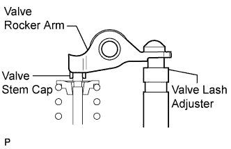
Install the 32 valve rocker arms as shown in the illustration.
-
-
INSTALL CAMSHAFT
-
Install the camshaft Click here.
-
-
INSTALL EXHAUST MANIFOLD SUB-ASSEMBLY
-
Install the exhaust manifold Click here.
-
-
CONNECT CABLE TO NEGATIVE BATTERY TERMINAL
Note
When disconnecting the cable, some systems need to be initialized after the cable from the cable is reconnected Click here.
-
INSPECT FOR EXHAUST GAS LEAK
-
INSPECT IGNITION TIMING
-
Warm up and stop the engine.
-
Allow the engine to warm up to a normal operating temperature.
-
-
Remove the engine room side cover LH.
-
Remove the engine room side cover RH.
-
Remove the upper radiator support seal.
-
Remove the V-bank cover.
-
When using the intelligent tester:
-
Connect the intelligent tester to the DLC3.
-
Start the engine and idle it.
-
Turn the intelligent tester ON.
-
Enter the following menus: Powertrain / Engine and ECT / Data List / Primary / IGN Advance.
Tech Tips
Refer to the intelligent tester operator's manual for further details.
Standard ignition timing 8 to 12° BTDC @ idle (transmission in neutral and A/C switch off) -
Disconnect the intelligent tester from the DLC3.
-
-
When not using the intelligent tester:
-
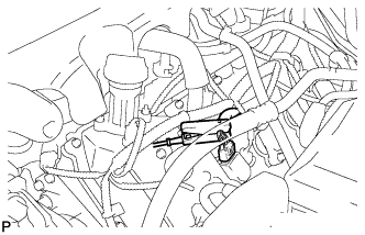
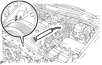
Connect the tester probe of a timing light to the wire of the ignition coil connector for the No. 1 cylinder.
Note
Use a timing light that detects primary signals.
-
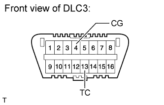
Using SST, connect terminals 13 (TC) and 4 (CG) of the DLC3.
- SST
- 09843-18040
Note
-
Confirm the terminal numbers before connecting them. Connecting the wrong terminals can damage the engine.
-
Switch off all accessories and the A/C before connecting the terminals.
-
Using the timing light, check the ignition timing.
Standard ignition timing 8 to 12° BTDC @ idle (transmission in neutral and A/C switch off) -
Remove SST from the DLC3.
-
Check the ignition timing.
Standard ignition timing 7 to 24° BTDC @ idle (transmission in neutral and A/C switch off) -
Disconnect the timing light from the engine.
-
-
Install the V-bank cover.
-
Install the upper radiator support seal.
-
Install the engine room side cover RH.
-
Install the engine room side cover LH.
-
-
INSPECT ENGINE IDLE SPEED
-
Warm up and stop the engine.
-
Allow the engine to warm up to a normal operating temperature.
-
-
When using the intelligent tester:
-
Connect the intelligent tester to the DLC3.
Note
Switch off all accessories and the A/C before connecting the intelligent tester.
-
Race the engine at 2500 rpm for approximately 90 seconds.
-
Turn the intelligent tester ON.
-
Enter the following menus: Powertrain / Engine and ECT / Data List / Primary / Engine Speed.
Standard idle speed 650 to 750 rpm (transmission in neutral and A/C switch off) Tech Tips
Refer to the intelligent tester operator's manual for further details.
If the idle speed is not as specified, check the air intake system.
-
Disconnect the intelligent tester from the DLC3.
-
-
When not using the intelligent tester:
-
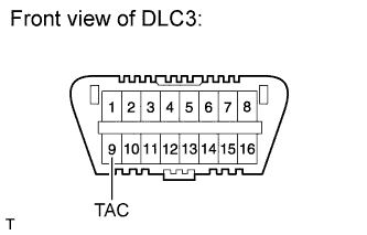
Using SST, connect the tachometer probe to terminal 9 (TAC) of the DLC3.
- SST
- 09843-18030
Note
-
Confirm the terminal number before connecting the probe. Connecting the probe to the wrong terminal can damage the engine.
-
Switch off all accessories and the A/C before connecting the probe.
-
Race the engine at 2500 rpm for approximately 90 seconds.
-
Check the idle speed.
Standard idle speed 650 to 750 rpm (transmission in neutral and A/C switch off) If the idle speed is not as specified, check the air intake system.
-
Disconnect the tachometer probe from the DLC3.
-
-