CAMSHAFT REMOVAL

-
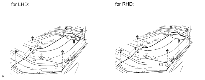
REMOVE ENGINE ROOM SIDE COVER LH
-
Remove the 7 clips and engine room side cover LH.
-
-
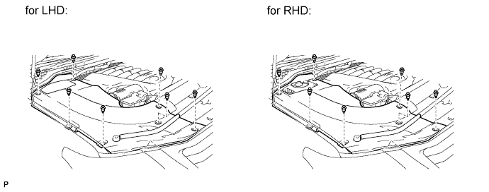
REMOVE ENGINE ROOM SIDE COVER RH
-
Remove the 7 clips and engine room side cover RH.
-
-
REMOVE UPPER RADIATOR SUPPORT SEAL
-
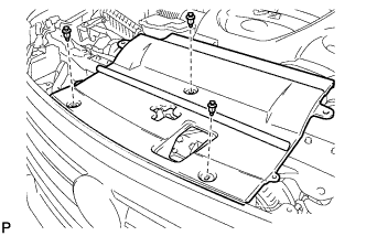
Remove the 3 clips and upper radiator support seal.
-
-
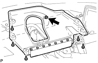
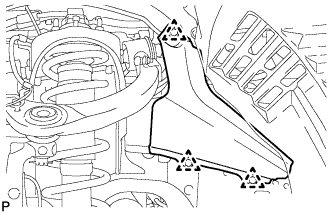
REMOVE V-BANK COVER SUB-ASSEMBLY
-
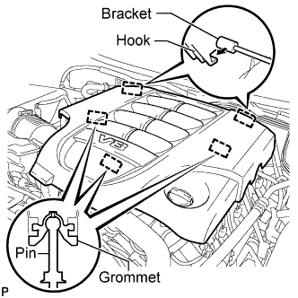
Raise the front of the V-bank cover to detach the 3 pins. Then remove the 2 V-bank cover hooks from the bracket, and remove the V-bank cover.
-
-
DISCHARGE FUEL SYSTEM PRESSURE
-
Discharge the fuel system pressure Click here.
-
-
DISCONNECT CABLE FROM NEGATIVE BATTERY TERMINAL
Note
-
w/ Navigation System:
After the engine switch is turned off, the HDD navigation system requires approximately 6 minutes to record various types of memory and settings. As a result, after turning the engine switch off, wait 6 minutes or more before disconnecting the cable from the negative (-) battery terminal.
-
When disconnecting the cable, some systems need to be initialized after the cable from the cable is reconnected Click here.
-
-
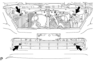
REMOVE FRONT FENDER SPLASH SHIELD SUB-ASSEMBLY LH
-
Remove the 3 bolts and 2 screws.
-
Turn the clip indicated by the arrow in the illustration to remove the front fender splash shield sub-assembly LH.
-
-
REMOVE FRONT FENDER SPLASH SHIELD SUB-ASSEMBLY RH
Tech Tips
Use the same procedure described for the LH side.
-
REMOVE NO. 1 ENGINE UNDER COVER SUB-ASSEMBLY
-
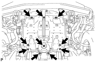
Remove the 10 bolts and No. 1 engine under cover.
-
-
REMOVE NO. 2 ENGINE UNDER COVER
-
Remove the 2 bolts and No. 2 engine under cover.
-
-
REMOVE FRONT FENDER APRON SEAL FRONT LH
-
Using a clip remover, remove the 4 clips and fender apron seal.
-
-
REMOVE FRONT FENDER APRON SEAL FRONT RH
-
Using a clip remover, remove the 3 clips and fender apron seal.
-
-
REMOVE RADIATOR GRILLE
-
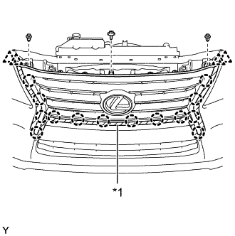
Text in Illustration *1 Protective Tape Put protective tape around the radiator grille assembly.
-
Remove the screw and 2 clips.
-
Detach the 4 clips and partially remove the upper radiator seal.
-
Detach the 14 claws and remove the radiator grille assembly.
-
w/ Wide View Front Monitor System:
Disconnect the connector.
-
-
REMOVE RADIATOR SIDE DEFLECTOR RH (w/o Air Cooled Transmission Oil Cooler)
-
Using a clip remover, remove the 5 clips and side deflector.
-
-
REMOVE RADIATOR SIDE DEFLECTOR LH
-
Using a clip remover, remove the 5 clips and side deflector.
-
-
REMOVE FRONT FENDER MAIN SEAL LH
-

Using a clip remover, detach the 3 clips and remove the fender main seal.
-
-
REMOVE FRONT FENDER MAIN SEAL RH
Tech Tips
Use the same procedure described for the LH side.
-
REMOVE FRONT WIPER ARM LH
-
Remove the nut, wiper arm and blade.
-
-
REMOVE FRONT WIPER ARM RH
-
Remove the nut, wiper arm and blade.
-
-
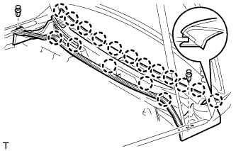
REMOVE HOOD TO COWL TOP SEAL
-
Using a clip remover, detach the 12 clips and 4 clamps, and remove the hood to cowl top seal.
-
-
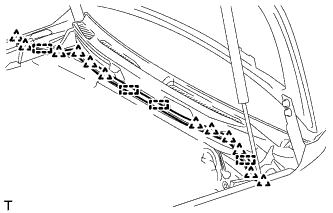
REMOVE COWL TOP VENTILATOR LOUVER SUB-ASSEMBLY
-
Disconnect the washer hose.
-
Remove the 2 clips.
-
Detach the 17 claws and remove the cowl top ventilator louver sub-assembly.
-
-
DRAIN ENGINE OIL
-
Remove the oil filler cap.
-
Remove the 2 bolts and No. 2 engine under cover seal.
-
Remove the oil pan drain plug and gasket, and drain the engine oil into a container.
-
Install a new gasket and the oil pan drain plug.
- Torque:
- 40 N*m { 408 kgf*cm, 30 ft.*lbf }
-
-
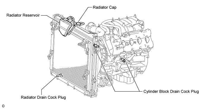
DRAIN ENGINE COOLANT
CAUTION:
Do not remove the radiator cap while the engine and radiator are still hot. Pressurized, hot engine coolant and steam may be released and cause serious burns.
-
Loosen the radiator drain cock plug.
Tech Tips
Collect the coolant in a container and dispose of it according to the regulations in your area.
-
Remove the radiator cap. Then drain the coolant from the radiator.
-
Loosen the 2 cylinder block drain cock plugs. Then drain the coolant from the engine.
-
Tighten the 2 cylinder block drain cock plugs.
- Torque:
- 13 N*m { 130 kgf*cm, 10 ft.*lbf }
-
Tighten the radiator drain cock plug by hand.
-
-
REMOVE AIR CLEANER HOSE ASSEMBLY
-
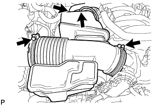
Disconnect the vacuum hose and No. 2 ventilation hose.
-
Loosen the 2 hose clamps.
-
Remove the air cleaner hose.
-
-
REMOVE AIR CLEANER ASSEMBLY
-
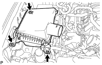
Remove the 3 bolts and air cleaner.
-
-
REMOVE NO. 1 RADIATOR HOSE
-
REMOVE NO. 2 RADIATOR HOSE
-
REMOVE FAN SHROUD
-
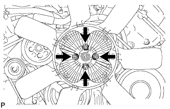
Loosen the 4 nuts holding the fluid coupling fan.
-
Remove the fan and generator V belt Click here.
-
Disconnect the reservoir hose from the upper radiator tank.
-
w/ Air Cooled Transmission Oil Cooler:
Detach the claw to open the flexible hose clamp.
-
Remove the 2 bolts and disconnect the oil cooler tube from the fan shroud.
-
Remove the 2 bolts holding the fan shroud.
-
Remove the 4 nuts of the fluid coupling fan, and then remove the shroud together with the coupling fan.
Note
Be careful not to damage the radiator core.
-
Remove the fan pulley.
-
-
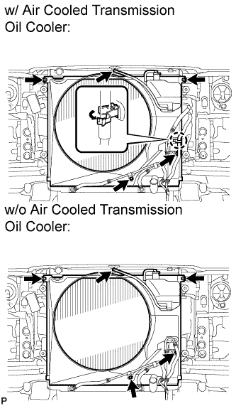
REMOVE RADIATOR ASSEMBLY
-
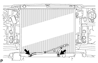
Disconnect the 2 oil cooler hoses.
-
Remove the 4 bolts and radiator.
-
-
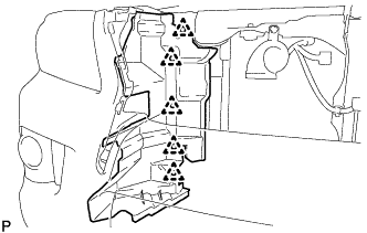
DISCONNECT ENGINE WIRE
-
Engine Room LH Side:
-
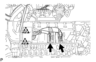
Remove the engine room relay block cover.
-
Disconnect the 2 connectors and 2 clips from the engine room junction block.
-
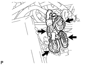
w/ Secondary Air Injection System:
Disconnect the 4 air injection control driver connectors and wire harness clamp.
-
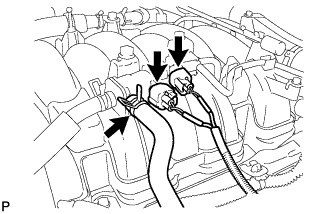
Disconnect the injector connector.
-
Disconnect the 4 ignition coil connectors.
-
Disconnect the 2 VVT sensor connectors.
-
Disconnect the 4 clamps.
-
Remove the 2 bolts and ground wire.
-
Disconnect the noise filter connector.
-
Disconnect the engine coolant temperature sensor connector.
-
Disconnect the 2 camshaft timing oil control valve connectors.
-
Disconnect the camshaft position sensor connector.
-
Disconnect the 3 clamps.
-
Disconnect the cooler compressor connector.
-
-
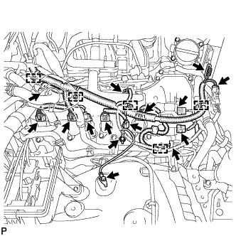
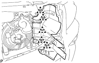
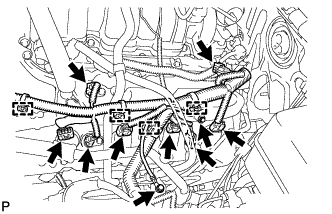
Engine Room RH Side:
-
Disconnect the 2 camshaft timing oil control valve connectors.
-
Disconnect the 4 ignition coil connectors.
-
Disconnect the injector connector.
-
Disconnect the 2 VVT sensor connectors.
-
Disconnect the noise filter connector.
-
Remove the 2 bolts and ground wire.
-
w/ Secondary Air Injection System:
Disconnect the 2 air pump connectors.
-
Disconnect the throttle position sensor and throttle control motor connector.
-
Disconnect the 5 clamps.
-
-
-
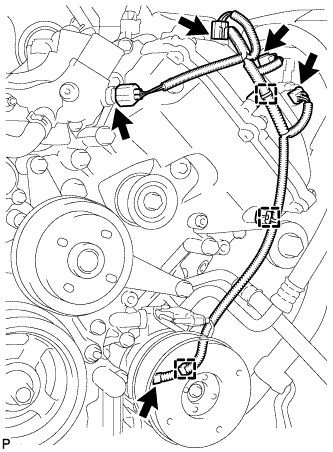
DISCONNECT AIR PUMP HOSE AND WIRE HARNESS (w/ Secondary Air Injection System)
-
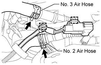
Disconnect the No. 2 and No. 3 air hoses.
-
Disconnect the 2 clamps.
-
-
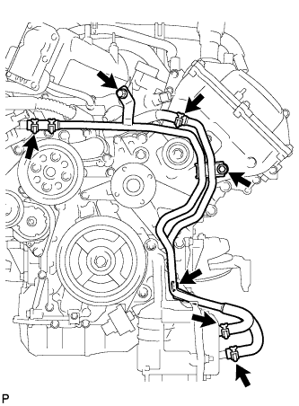
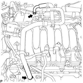
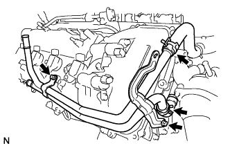
DISCONNECT NO. 2 WATER BY-PASS PIPE
-
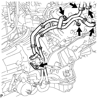
Disconnect the 3 hoses.
-
Remove the 3 bolts and disconnect the No. 2 water by-pass pipe from the cylinder head cover.
-
-
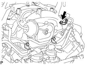
DISCONNECT COOLER COMPRESSOR ASSEMBLY
-
Remove the 3 bolts, nut and stud bolt, and disconnect the cooler compressor.
Tech Tips
It is not necessary to completely remove the compressor. With the hoses connected to the compressor, hang the compressor on the vehicle body with a rope.
-
-
DISCONNECT NO. 2 FUEL TUBE SUB-ASSEMBLY
-
Remove the 2 bolts and disconnect the fuel tube.
-
-
REMOVE OIL FILTER ELEMENT
-
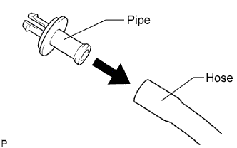
Connect a hose with an inside diameter of 15 mm (0.591 in.) to the pipe.
-
Remove the oil filter drain plug.
-
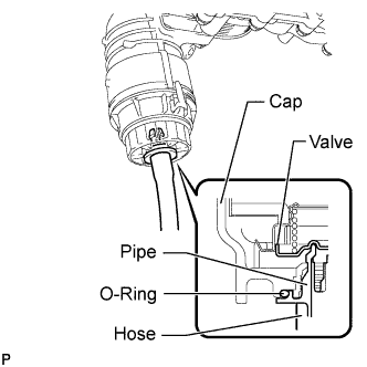
Install the pipe to the oil filter cap.
Note
If the O-ring is removed with the drain plug, install the O-ring together with the pipe.
Tech Tips
Use a container to catch the draining oil.
-
Check that oil is drained from the oil filter. Then disconnect the pipe and remove the O-ring as shown in the illustration.
-
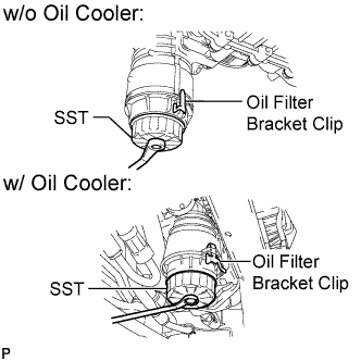
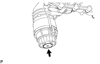
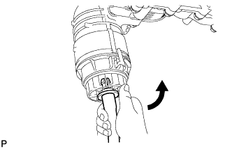
Using SST, remove the oil filter cap.
- SST
- 09228-06501
Note
Do not remove the oil filter bracket clip.
-
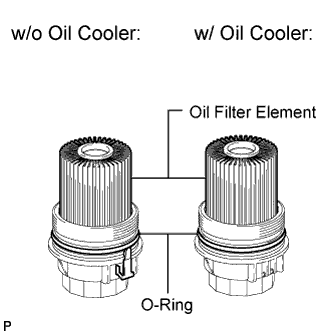
Remove the oil filter element and O-ring from the oil filter cap.
Note
Be sure to remove the cap O-ring by hand, without using any tools, to prevent damage to the cap O-ring groove.
-
-
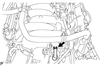
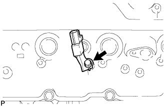
REMOVE OIL PRESSURE SENDER GAUGE ASSEMBLY
-
Disconnect the sender gauge connector.
-
Remove the oil pressure sender gauge.
-
-
REMOVE NO. 2 WATER BY-PASS PIPE SUB-ASSEMBLY (w/ Oil Cooler)
-
Remove the 3 bolts.
-
Disconnect the 4 hoses and remove the water by-pass pipe.
-
-
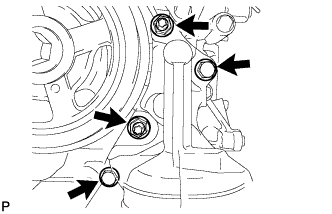
REMOVE NO. 1 OIL COOLER BRACKET (w/ Oil Cooler)
-
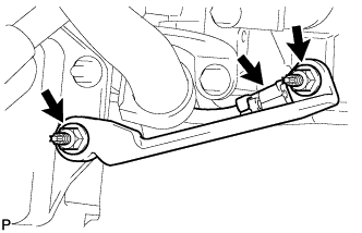
Remove the 2 nuts and bracket.
-
Disconnect the ground wire from the cylinder block.
-
-
REMOVE OIL FILTER BRACKET (w/ Oil Cooler)
-
Remove the 2 bolts, 2 nuts and filter bracket.
-
Remove the 2 O-rings.
-
-
REMOVE OIL FILTER BRACKET (w/o Oil Cooler)
-
Remove the 2 bolts, 2 nuts and oil filter bracket.
-
Remove the 2 O-rings.
-
-
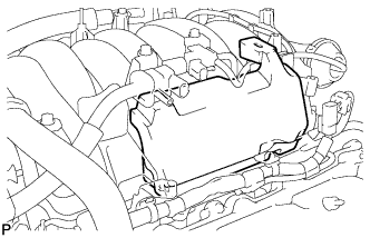
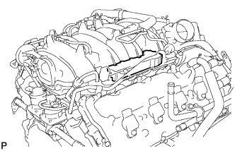
REMOVE INTAKE MANIFOLD
-
Disconnect the ventilation hose from the ventilation pipe of the cylinder head cover LH and RH.
-
Disconnect the 2 water by-pass hoses.
-
Disconnect the throttle body connector.
-
Disconnect the No. 1 ventilation hose.
-
Disconnect the purge VSV connector.
-
Disconnect the purge line hose from the purge VSV.
-
Disconnect the vacuum switching valve connector (for ACIS).
-
Remove the No. 1 engine cover sub-assembly.
-
Remove the No. 3 engine cover.
-
Disconnect the 3 wire clamps from the 3 wire brackets.
-
Remove the bolt and wire bracket from the intake manifold.
-
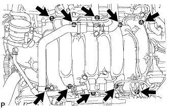
Remove the 2 nuts, 8 bolts, intake manifold and 2 gaskets.
-
-
DISCONNECT VANE PUMP ASSEMBLY
-
Disconnect the 2 clamps and power steering oil pressure switch connector.
-
Remove the 2 bolts and disconnect the vane pump.
-
-
REMOVE ENGINE OIL LEVEL DIPSTICK GUIDE
-
Remove the dipstick.
-
Remove the bolt and dipstick guide.
-
Remove the O-ring from the dipstick guide.
-
-
DISCONNECT OIL COOLER PIPE ASSEMBLY
-
Remove the 2 bolts and disconnect the oil cooler pipe.
-
-
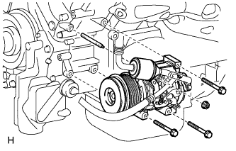
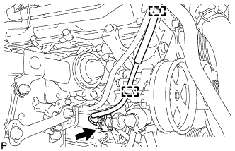
REMOVE GENERATOR ASSEMBLY
-
for 150A Type:
-
for 180A Type:
-
-
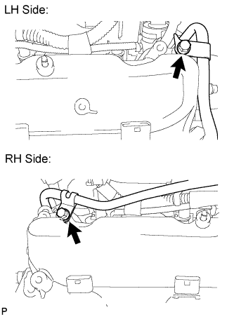
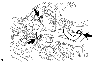
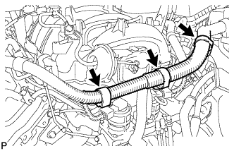
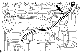
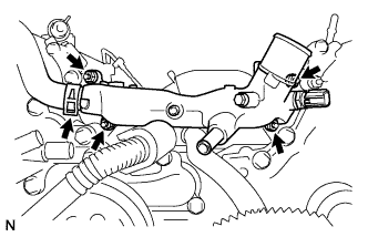
REMOVE NO. 1 WATER BY-PASS HOSE
-
Remove the No. 1 water by-pass hose by disconnecting the hose from the water inlet housing and front water by-pass joint.
-
-
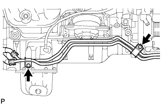
REMOVE WATER BY-PASS PIPE SUB-ASSEMBLY
-
w/ Secondary Air Injection System:
Remove the bolt and disconnect the air tube.
-
Disconnect the 2 hoses.
-
Remove the 2 bolts and water by-pass pipe.
-
-
REMOVE FRONT WATER BY-PASS JOINT
-
Disconnect the No. 2 water by-pass hose from the water by-pass joint.
-
Remove the 4 nuts, water by-pass joint and 2 gaskets.
-
-
REMOVE NO. 2 ENGINE COVER
-
REMOVE NO. 1 ENGINE COVER
-
REMOVE AIR PIPE SUB-ASSEMBLY (w/ Secondary Air Injection System)
-
Remove the bolt, disconnect the 2 hoses, and remove the air pipe.
-
-
REMOVE WATER INLET HOUSING
-
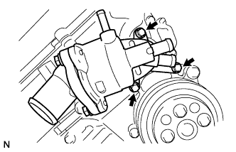
Remove the 3 bolts, water inlet housing and gasket.
-
-
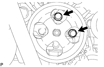
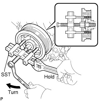
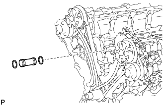
REMOVE WATER PUMP PULLEY
-
Using SST, hold the water pump pulley.
- SST
- 09960-10010 ( 09962-01000, 09963-01000 )
-
Remove the 4 bolts and water pump pulley.
-
-
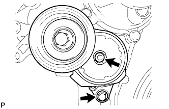
REMOVE NO. 1 IDLER PULLEY SUB-ASSEMBLY
-
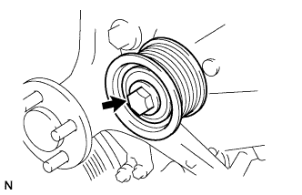
Remove the bolt and idler pulley.
-
-
REMOVE FLUID COUPLING BRACKET
-
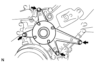
Remove the 4 bolts and fluid coupling bracket.
-
-
REMOVE V-RIBBED BELT TENSIONER ASSEMBLY
-
Remove the standard bolt, 6 mm hexagon wrench bolt and belt tensioner.
-
-
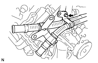
REMOVE IGNITION COIL ASSEMBLY
-
Remove the 8 bolts and 8 ignition coils.
-
-
REMOVE CYLINDER HEAD COVER SUB-ASSEMBLY LH
-
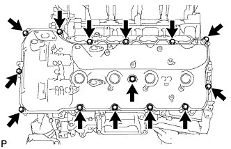
Remove the 14 bolts, seal washer, cylinder head cover and gasket.
Tech Tips
Make sure the removed parts are returned to the same places they were removed from.
-
Remove the 5 gaskets from the camshaft bearing caps (No. 2, No. 3).
-
-
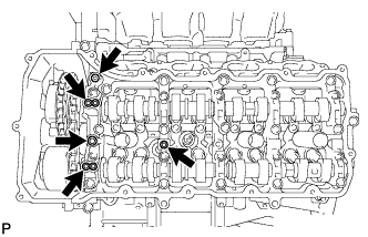
REMOVE CYLINDER HEAD COVER SUB-ASSEMBLY RH
-
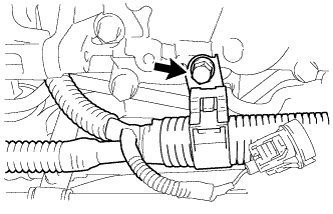
Remove the bolt and noise filter.
-
Remove the 14 bolts, seal washer, cylinder head cover and gasket.
Tech Tips
Make sure the removed parts are returned to the same places they were removed from.
-
Remove the 5 gaskets from the camshaft bearing caps (No. 1, No. 3).
-
-
REMOVE SPARK PLUG TUBE GASKET
-
Bend the 4 ventilation baffle plate claws on the cylinder head cover to an angle of 90° or more.
-
Using a screwdriver, pry out the gaskets.
Tech Tips
Tape the screwdriver tip before use.
Note
-
Be careful not to damage the cylinder head cover.
-
Be careful not to damage the gasket when removing it, as the removed gasket needs to be used when installing a new one.
-
-
-
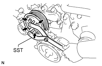
REMOVE CRANKSHAFT PULLEY
-
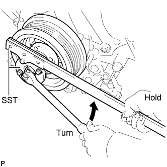
Using SST, loosen the crankshaft pulley set bolt until 2 or 3 threads are engaged.
- SST
- 09213-70011 ( 09213-70020 )
- 09330-00021
-
Using the pulley set bolt and SST, remove the crankshaft pulley.
- SST
- 09950-50013 ( 09951-05010, 09952-05010, 09953-05010, 09954-05011 )
-
-
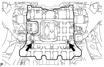
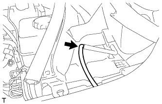
DISCONNECT WIRE HARNESS CLAMP BRACKET
-
Remove the bolt and disconnect the bracket.
-
-
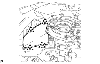
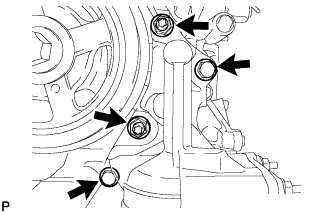
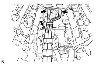
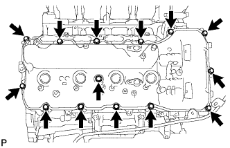
REMOVE TIMING CHAIN COVER SUB-ASSEMBLY
-
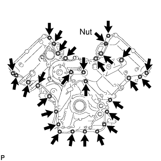
Remove the 28 bolts and nut shown in the illustration.
-
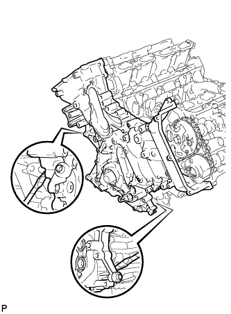
Remove the timing chain cover by prying between the timing chain cover and cylinder head or cylinder block with a screwdriver as shown in the illustration.
Note
Be careful not to damage the contact surfaces of the cylinder head, cylinder block and chain cover.
Tech Tips
Tape the screwdriver tip before use.
-
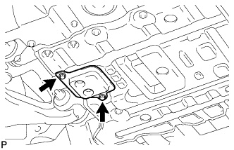
Remove the oil pump gasket from the cylinder block.
-
Remove the O-ring from the oil pan.
-
-
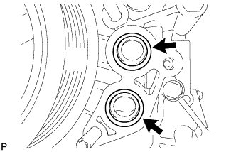
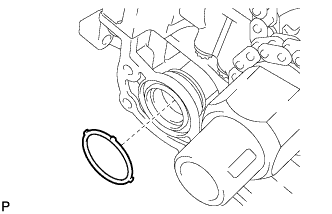
REMOVE WATER INLET PIPE
-
Remove the water inlet pipe.
-
Remove the 2 O-rings from the water inlet pipe.
-
-
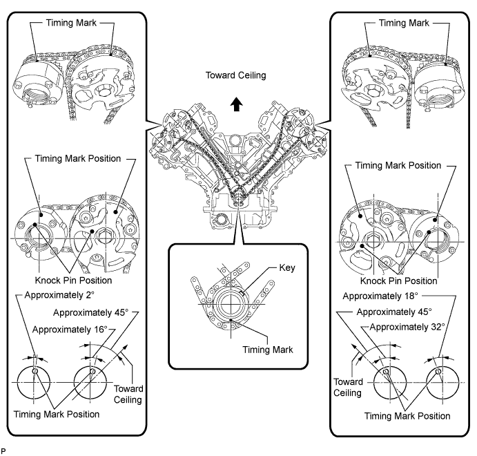
SET NO. 1 CYLINDER TO TDC/COMPRESSION
-
Temporarily install the crankshaft pulley bolt.
-
Rotate the crankshaft clockwise so that the timing marks on the crankshaft timing sprocket and camshaft timing gears are as shown in the illustration.
Tech Tips
If the timing marks do not align, rotate the crankshaft clockwise again and align the timing marks.
-
-
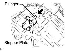
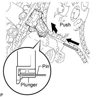
REMOVE NO. 1 CHAIN TENSIONER ASSEMBLY LH
-
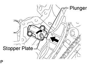
Move the stopper plate clockwise to release the lock, and push the plunger deep into the tensioner.
-
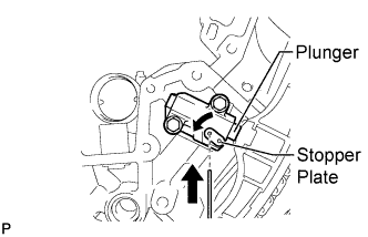
Move the stopper plate counterclockwise to set the lock, and insert a hexagon wrench into the stopper plate hole.
-
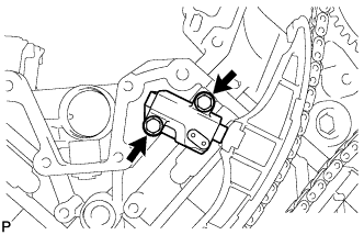
Remove the 2 bolts, chain tensioner and gasket.
-
-
REMOVE NO. 1 CHAIN TENSIONER SLIPPER LH
-
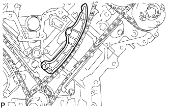
REMOVE NO. 1 CHAIN VIBRATION DAMPER LH
-
Remove the 2 bolts and chain vibration damper.
-
-
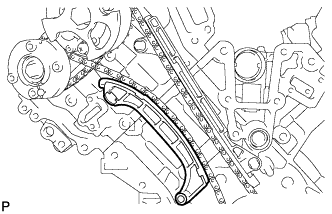
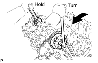
REMOVE NO. 1 CHAIN SUB-ASSEMBLY LH
-
While pushing down the No. 3 chain tensioner, insert a pin of 1.0 mm (0.0394 in.) into the hole to fix it in place.
-
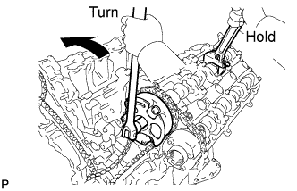
Hold the hexagonal portion of the camshaft with a wrench and loosen the bolt.
Note
-
Be careful not to damage the cylinder head with the wrench.
-
Do not disassemble the camshaft timing gear.
-
-
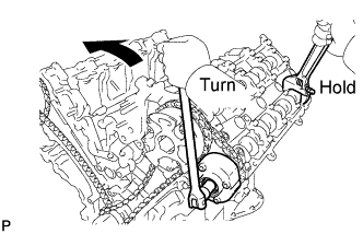
Hold the hexagonal portion of the camshaft with a wrench and loosen the bolt.
Note
Be careful not to damage the cylinder head with the wrench.
-
Remove the 2 bolts. Then with the No. 1 and No. 2 chains still connected to the gears, remove the camshaft timing gear, camshaft timing exhaust gear and crankshaft timing sprocket LH.
-
Remove the No. 1 and No. 2 chains from the gears.
-
-
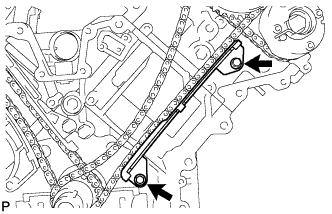
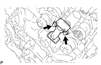
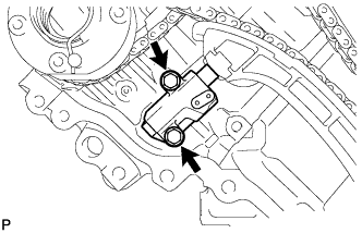
REMOVE NO. 3 CHAIN TENSIONER ASSEMBLY
-
Remove the 2 bolts and chain tensioner.
-
-
REMOVE NO. 1 CHAIN TENSIONER ASSEMBLY RH
-
Move the stopper plate clockwise to release the lock, and push the plunger deep into the tensioner.
-
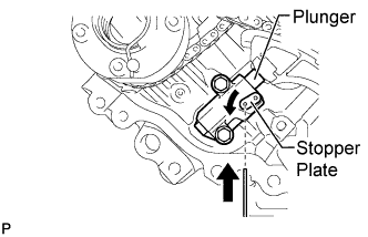
Move the stopper plate counterclockwise to set the lock, and insert a hexagon wrench into the stopper plate hole.
-
Remove the 2 bolts and chain tensioner.
-
-
REMOVE NO. 1 CHAIN TENSIONER SLIPPER RH
-
REMOVE NO. 1 CHAIN VIBRATION DAMPER RH
-
Remove the 2 bolts and vibration damper.
-
-
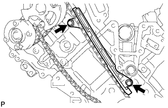
REMOVE NO. 1 CHAIN SUB-ASSEMBLY RH
-
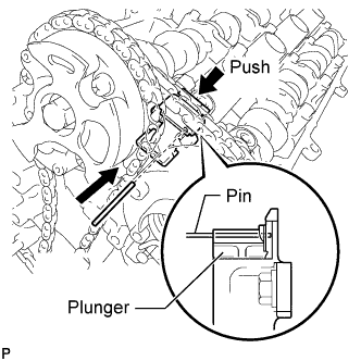
While raising up the No. 2 chain tensioner, insert a pin of 1.0 mm (0.0394 in.) into the hole to fix it in place.
-
Hold the hexagonal portion of the camshaft with a wrench and loosen the bolt.
Note
-
Be careful not to damage the cylinder head with the wrench.
-
Do not disassemble the camshaft timing gear.
-
-
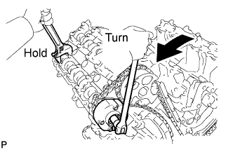
Hold the hexagonal portion of the camshaft with a wrench and loosen the bolt.
Note
Be careful not to damage the cylinder head with the wrench.
-
Remove the 2 bolts. Then with the No. 1 and No. 2 chains still connected to the gears, remove the camshaft timing gear, camshaft timing exhaust gear and crankshaft timing sprocket RH.
-
Remove the No. 1 and No. 2 chains from the gears.
-
-
REMOVE NO. 2 CHAIN TENSIONER ASSEMBLY
-
Remove the 2 bolts and chain tensioner.
-
-
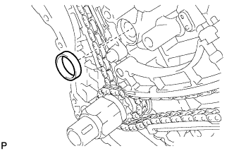
REMOVE CRANKSHAFT TIMING GEAR KEY
-
Using a screwdriver, remove the 2 timing gear keys from the crankshaft.
-
-
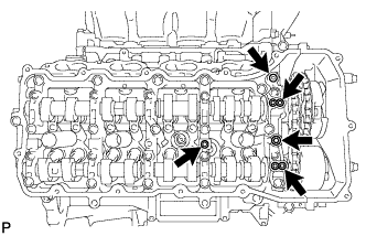
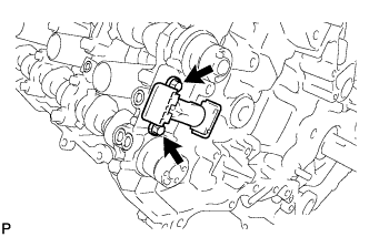
REMOVE CAMSHAFT BEARING CAP LH
-
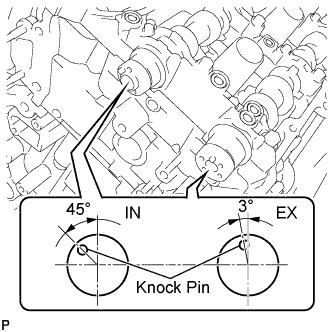
Make sure that the knock pin of the camshaft is positioned as shown in the illustration.
-
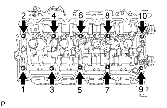
Uniformly loosen and remove the 10 bearing cap bolts in the sequence shown in the illustration.
-
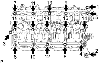
Uniformly loosen and remove the 18 bearing cap bolts in the sequence shown in the illustration.
Note
Uniformly loosen the bolts while keeping the camshaft level.
-
Remove the 6 bearing caps.
Tech Tips
Arrange the removed parts in the correct order.
-
Remove the No. 3 and No. 4 camshafts.
Tech Tips
Arrange the removed parts in the correct order.
-
-
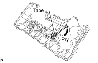
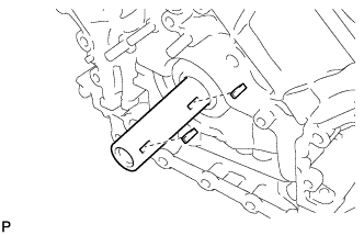
REMOVE CAMSHAFT HOUSING SUB-ASSEMBLY LH
-
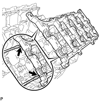
Remove the camshaft housing by prying between the cylinder head and camshaft housing with a screwdriver.
Tech Tips
Tape the screwdriver tip before use.
Note
Be careful not to damage the contact surfaces of the cylinder head and camshaft housing.
-
-
REMOVE CAMSHAFT BEARING CAP RH
-
Make sure that the knock pin of the camshaft is positioned as shown in the illustration.
-
Uniformly loosen and remove the 10 bearing cap bolts in the sequence shown in the illustration.
-
Uniformly loosen and remove the 18 bearing cap bolts in the sequence shown in the illustration.
Note
Uniformly loosen the bolts while keeping the camshaft level.
-
Remove the 6 bearing caps.
Tech Tips
Arrange the removed parts in the correct order.
-
Remove the No. 1 and No. 2 camshafts.
Tech Tips
Arrange the removed parts in the correct order.
-
-
REMOVE CAMSHAFT HOUSING SUB-ASSEMBLY RH
-
Remove the camshaft housing by prying between the cylinder head and camshaft housing with a screwdriver.
Tech Tips
Tape the screwdriver tip before use.
Note
Be careful not to damage the contact surfaces of the cylinder head and camshaft housing.
-