ENGINE UNIT INSTALLATION

-
INSTALL NOISE FILTER
-
for Bank 2:
Install the noise filter to the cylinder head cover with the bolt.
- Torque:
- 10 N*m { 102 kgf*cm, 7 ft.*lbf }
-
for Bank 1:
Install the noise filter to the cylinder head cover with the bolt.
- Torque:
- 10 N*m { 102 kgf*cm, 7 ft.*lbf }
-
-
INSTALL IGNITION COIL ASSEMBLY
-
Install the 8 ignition coils with the 8 bolts.
- Torque:
- 10 N*m { 102 kgf*cm, 7 ft.*lbf }
-
-
INSTALL NO. 11 WATER BY-PASS HOSE
-
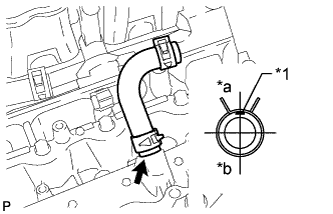
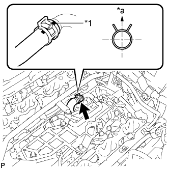
Text in Illustration *1 Paint Mark *a Rear *b Front Install the No. 11 water by-pass hose.
Tech Tips
-
When connecting the hose, make sure the paint marks and clips are as shown in the illustration.
-
The direction of the hose clamp is indicated in the illustration.
-
-
-
INSTALL ENGINE WIRE
-
Attach the 3 wire harness clamps to install the engine wire.
-
Connect the 4 knock sensor connectors.
-
Install the bolt.
- Torque:
- 8.0 N*m { 82 kgf*cm, 71 in.*lbf }
-
-
INSTALL NO. 1 ENGINE COVER
-
INSTALL NO. 2 ENGINE COVER
-
INSTALL SEPARATOR CASE
-
Install the separator case with the 4 bolts.
- Torque:
- 10 N*m { 102 kgf*cm, 7 ft.*lbf }
-
-
INSTALL NO. 1 IDLER PULLEY SUB-ASSEMBLY
-
Install the No. 1 idler pulley with the bolt.
- Torque:
- 43 N*m { 438 kgf*cm, 32 ft.*lbf }
-
-
INSTALL WATER PUMP PULLEY
-
Temporarily install the water pump pulley with the 4 bolts.
-
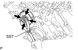
Using SST, hold the water pump pulley and tighten the 4 bolts.
- SST
- 09960-10010 ( 09962-01000, 09963-01000 )
- Torque:
- 21 N*m { 214 kgf*cm, 15 ft.*lbf }
-
-
INSTALL NO. 1 WATER BY-PASS HOSE
-
INSTALL NO. 2 WATER BY-PASS PIPE SUB-ASSEMBLY
-
Connect the 4 hoses.
-
Install the water by-pass pipe with the 2 bolts.
- Torque:
- 10 N*m { 102 kgf*cm, 7 ft.*lbf }
-
-
INSTALL NO. 3 ENGINE COVER
-
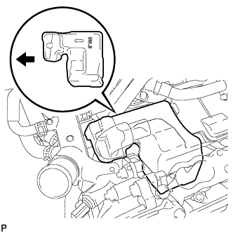
Install the No. 3 engine cover.
Text in Illustration 
Engine Front Tech Tips
Position the No. 3 engine cover so that the arrow mark faces the front of the engine and install it.
-
-
INSTALL NO. 4 ENGINE COVER
-
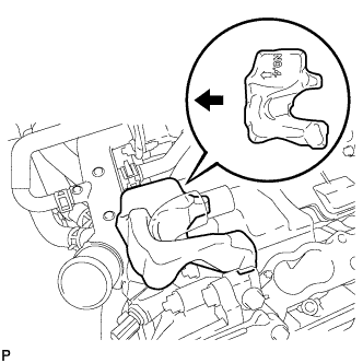
Install the No. 4 engine cover.
Text in Illustration Engine Front Tech Tips
Position the No. 4 engine cover so that the arrow mark faces the front of the engine and install it.
-
-
INSTALL NO. 2 FUEL DELIVERY PIPE SUB-ASSEMBLY
-
Install the 2 delivery pipe spacers and 4 insulators to the cylinder head LH.
-
Install the delivery pipe together with the injectors to the cylinder head LH.
-
Install the 2 bolts.
- Torque:
- 21 N*m { 214 kgf*cm, 15 ft.*lbf }
Note
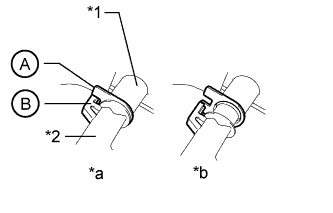
Make sure that the part of the injector labeled B is between the parts of the delivery pipe labeled A.
Text in Illustration *1 Fuel Delivery Pipe *2 Fuel Injector *a CORRECT *b INCORRECT -
Connect the No. 7 wire harness connector.
-
-
INSTALL FUEL DELIVERY PIPE SUB-ASSEMBLY
-
Install the 2 delivery pipe spacers and 4 insulators to the cylinder head RH.
-
Install the delivery pipe together with the injectors to the cylinder head RH.
-
Install the 2 bolts.
- Torque:
- 21 N*m { 214 kgf*cm, 15 ft.*lbf }
Note
Make sure that the part of the injector labeled B is between the parts of the delivery pipe labeled A.
Text in Illustration *1 Fuel Delivery Pipe *2 Fuel Injector *a CORRECT *b INCORRECT -
Connect the No. 6 wire harness connector.
-
-
INSTALL FRONT NO. 1 ENGINE MOUNTING BRACKET LH
-
Install the front No. 1 engine mounting bracket LH with the 4 bolts.
- Torque:
- 35 N*m { 357 kgf*cm, 26 ft.*lbf }
-
-
INSTALL FRONT NO. 1 ENGINE MOUNTING BRACKET RH
-
Install the front No. 1 engine mounting bracket RH with the 4 bolts.
- Torque:
- 35 N*m { 357 kgf*cm, 26 ft.*lbf }
-
-
INSTALL NO. 1 EGR PIPE BRACKET
-
Install the No. 1 EGR pipe bracket with the 3 bolts.
- Torque:
- 21 N*m { 214 kgf*cm, 15 ft.*lbf }
-
-
INSTALL NO. 1 WATER OUTLET PIPE
-
Install the No. 1 water outlet pipe with the 2 bolts.
- Torque:
- 10 N*m { 102 kgf*cm, 7 ft.*lbf }
-
-
CONNECT NO. 11 WATER BY-PASS HOSE
-
Text in Illustration *1 Paint Mark *a Upper Side Connect the No. 11 water by-pass hose.
Tech Tips
The direction of the hose clamp is indicated in the illustration.
-
-
INSTALL NO. 8 WATER BY-PASS HOSE
-
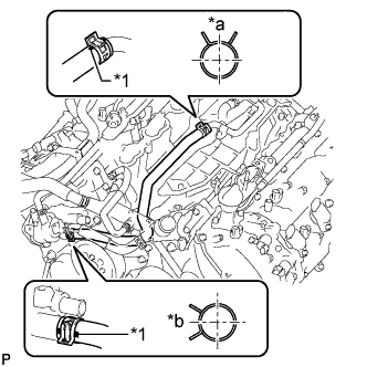
Text in Illustration *1 Paint Mark *a Upper Side *b Front Install the No. 8 water by-pass hose.
Tech Tips
-
When connecting the hose, make sure the paint marks and clips are as shown in the illustration.
-
The direction of each hose clamp is indicated in the illustration.
-
-
-
INSTALL NO. 2 WATER BY-PASS PIPE
-
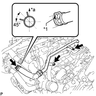
Text in Illustration *1 Paint Mark *a Upper Side Install the No. 2 water by-pass pipe with the 2 bolts and connect the hose.
- Torque:
- 10 N*m { 102 kgf*cm, 7 ft.*lbf }
Tech Tips
-
When connecting the hose, make sure the paint marks and clips are as shown in the illustration.
-
The direction of each hose clamp is indicated in the illustration.
-
-
INSTALL NO. 3 AIR TUBE
-
Install the No. 3 air tube with the bolt.
- Torque:
- 10 N*m { 102 kgf*cm, 7 ft.*lbf }
-
-
INSTALL NO. 4 AIR TUBE
-
Install the No. 4 air tube with the bolt.
- Torque:
- 10 N*m { 102 kgf*cm, 7 ft.*lbf }
-
-
INSTALL AIR SWITCHING VALVE ASSEMBLY (for Bank 2)
-
INSTALL AIR SWITCHING VALVE ASSEMBLY (for Bank 1)
-
INSTALL FUEL TUBE SUB-ASSEMBLY
-
Install the fuel tube Click here.
-
Install the 2 bolts.
- Torque:
- 10 N*m { 102 kgf*cm, 7 ft.*lbf }
-
-
INSTALL FUEL HOSE
-
Install the fuel hose Click here.
-
Install the fuel pipe clamp.
-
Connect the 2 clamps.
-
-
INSTALL ENGINE WIRE